
Furniture assembly

a technology for furniture and brackets, applied in the field of furniture assemblies, can solve the problems of limiting the maximum load on the shelf, affecting so as to prevent the twisting of the stretcher, reduce the structural integrity of the shelving assembly, and reduce the effect of the load laterally

Inactive Publication Date: 2011-07-28
ELEVATIONS
View PDF39 Cites 0 Cited by
  • Summary
  • Abstract
  • Description
  • Claims
  • Application Information

AI Technical Summary

Benefits of technology

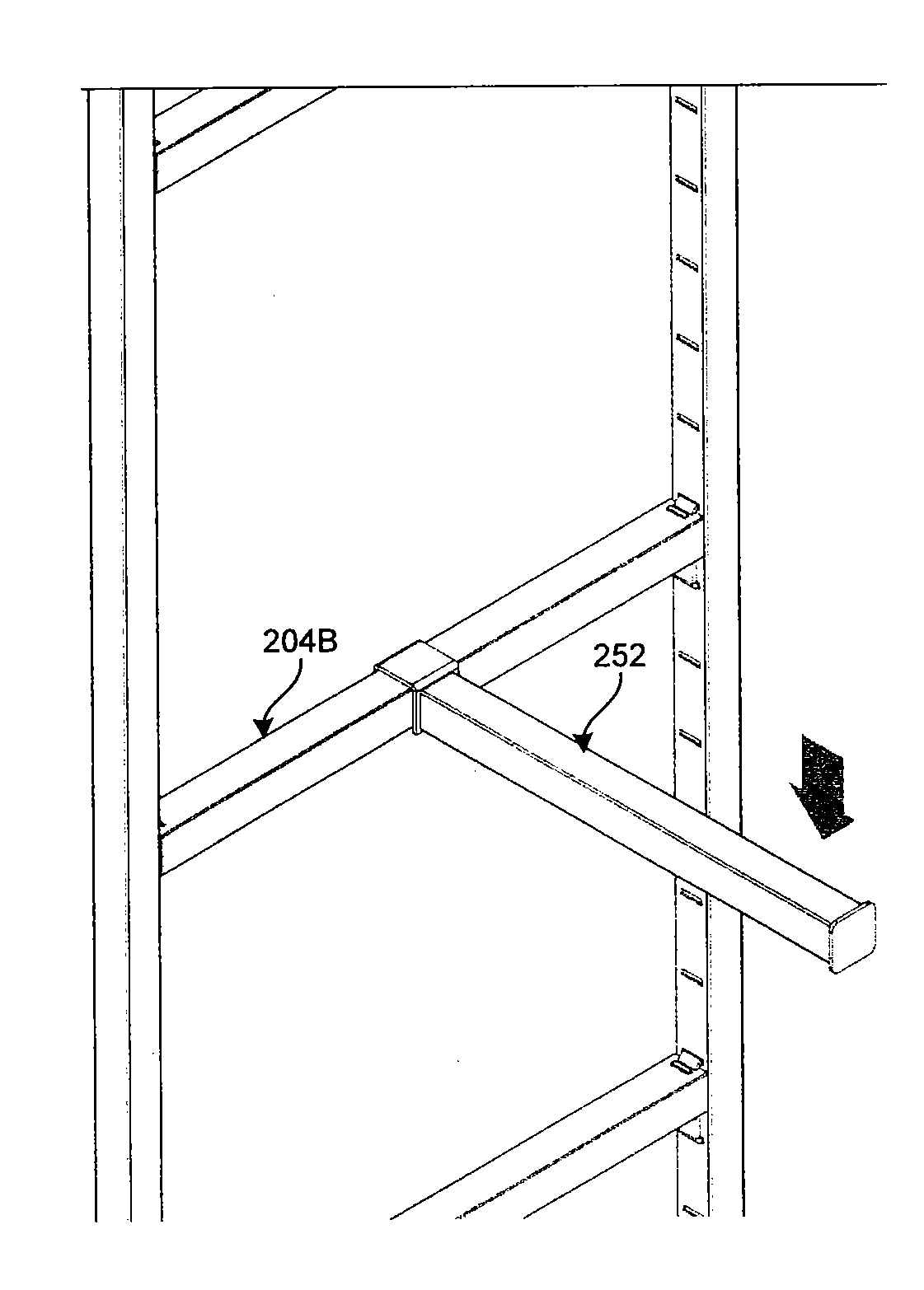
[0012]In this manner, the stretcher is connected and interlocked between the multiple beams. The brackets, by virtue of its lock features, do not require a screw or other permanent fixture mechanisms (e.g., bolting, welding, etc.) to be locked within the beam. Similarly, the stretcher simply slides over the protruding surface feature of the bracket, eliminating the need for any permanent fixture mechanisms to secure the brackets or the beams. Despite the lack of permanent fixture mechanisms, the shelving assembly described herein possesses the structural integrity offered by certain prior art permanent fixture mechanisms. For example, the stretcher and bracket assembly lock the stretcher in position—because the slots of the stretcher are slid over the protruding surface, the stretcher is locked in that position and cannot be moved or slid from the position. Accordingly, the beams, by virtue of being held in place by the interconnected stretcher, are also held in position. Any load on the beams that may cause the beams to splay (i.e., bulge outwards or inwards) is transferred to the stretcher. The stretcher, by virtue of being locked in position by the bracket, dissipates the load laterally to the bottom of the beam structure. Such an arrangement also prevents the stretcher from “twisting” when a lateral load is attached in the form of, for example, an accessory affixed to the stretcher. Furthermore, it can be envisioned that the structural integrity of the shelving assembly increases with the increase in number of stretchers used to interconnect the beams.
[0013]In addition to providing the structural-integrity advantages discussed above, the improved furniture assembly described herein also provides aesthetic advantages over the permanent fixture assemblies. Because, in embodiments, the protruding extension slides completely within the slot extension, the features of the bracket are hidden to a casual observer. There are no unsightly screw extensions or coverings that may impair the aesthetic appeal of the shelf. Another advantage of the shelving assembly discussed herein is the easy usability and flexibility. A user can simply slide the stretcher out of the brackets without the need for any tools, and further easily refit the stretcher at another location of the beam by simply inserting the brackets and sliding the stretcher over the protruding extensions of the brackets. There is simply no need for any tools or special labor in the attachment and removal of the stretchers.

Problems solved by technology

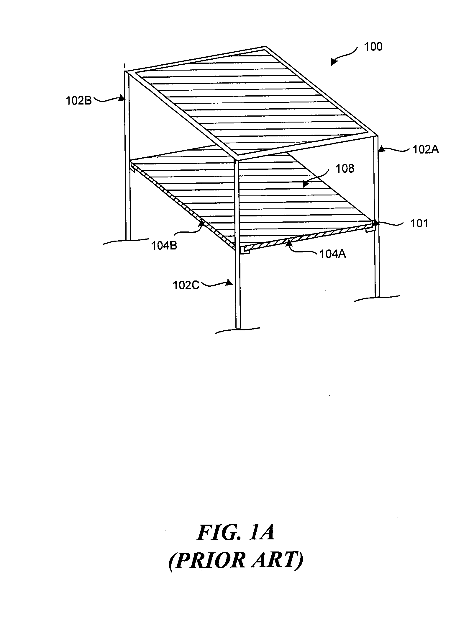
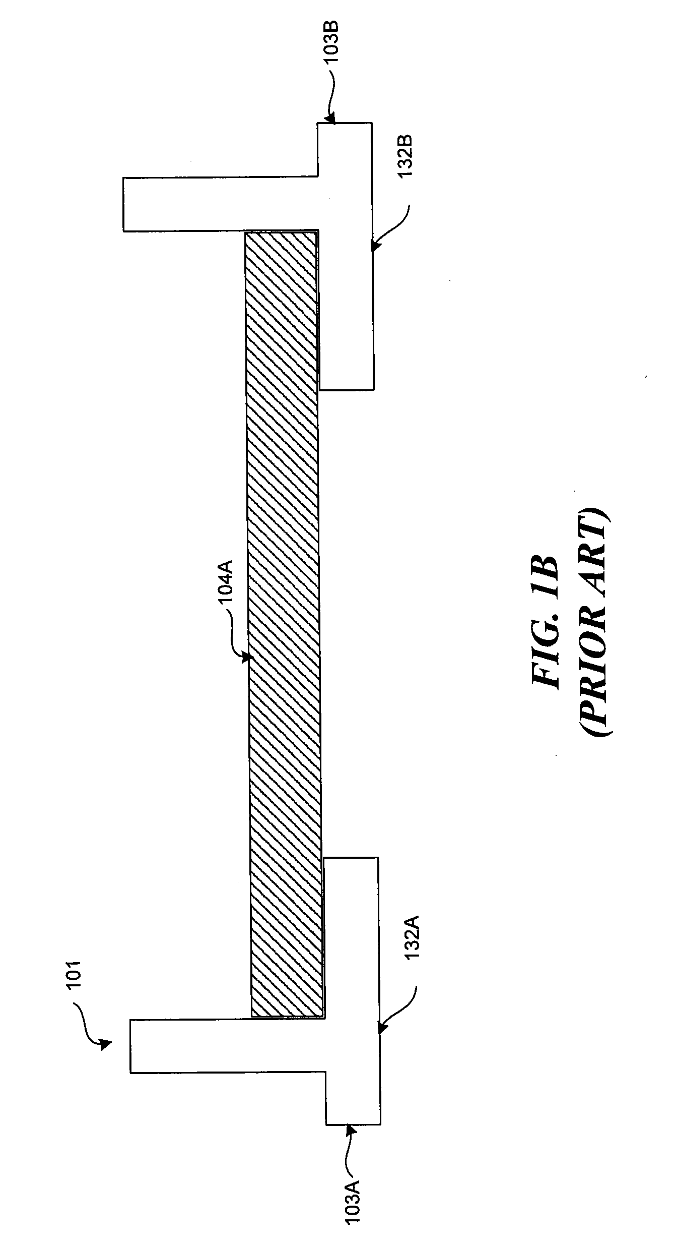
However, a problem with such an arrangement is that the structural integrity of the shelving assembly is limited by the integrity of the brackets.
Specifically, the maximum load on the shelf is typically limited by the strength of the bracket, no matter what system is used.
A high load on the shelf may cause the shelf or stretcher to bend, and this bending, in conjunction with the splaying of the uprights, may cause the stretcher or bracket to fail.
Additionally, the stretcher is not “locked” in place, and so further limits the sturdiness of the eventual shelving assembly.
The support bracket assembly does nothing to prevent the beams from splaying, further contributing to structural integrity issues.
While this assembly may solve the problem of the stretcher sliding off the brackets (and in some cases, even of the twisting issue mentioned above), the predominant structural issue of splaying is still an issue with this design.
First, the screw assembly requires tools and additional work for connecting the stretcher to the beams, making these assemblies more permanent in nature than the examples of FIGS. 1A and 1B (where the stretchers can easily be inserted and removed at will).
Second, the screws reduce the aesthetic value of the shelving assembly—the screws are either visible on the outside of the beams, or a special covering may be needed over the beams to cover visible portions of the screw-heads.
While this would prevent the structural integrity issues associated with splaying, such assemblies offer limited flexibility and maneuverability.
While the permanent fixture may be acceptable in an industrial warehouse where the stretcher assembly is permanently placed in position, such an assembly would simply not work in a scenario where the shelves and / or the stretchers need to be rearranged and refitted on a per-need basis (e.g., in a departmental clothing store where the shelves need to be constantly rearranged and refitted to effectively display merchandise).

Method used


Image

  • Furniture assembly
  • Furniture assembly
  • Furniture assembly

Examples


Embodiment Construction

[0022]Various examples of the invention will now be described. The following description provides specific details for a thorough understanding and enabling description of these examples. One skilled in the relevant art will understand, however, that the invention may be practiced without many of these details. Likewise, one skilled in the relevant art will also understand that the invention can include many other obvious features not described in detail herein. Additionally, some well-known structures or functions may not be shown or described in detail below, so as to avoid unnecessarily obscuring the relevant description.

[0023]The terminology used below is to be interpreted in its broadest reasonable manner, even though it is being used in conjunction with a detailed description of certain specific examples of the invention. Indeed, certain terms may even be emphasized below; however, any terminology intended to be interpreted in any restricted manner will be overtly and specific...


PUM

PropertyMeasurementUnit
distanceaaaaaaaaaa
heightaaaaaaaaaa
strengthaaaaaaaaaa

Abstract

Discussed herein is an improved furniture assembly, where stretchers are secured between beams of a shelving assembly using brackets. The stretchers include at least one hollow slot that is sufficiently wide to allow the slot to be slid over a protruding surface of the bracket. In embodiments, the brackets have a protruding surface that is substantially parallel to a base surface of the bracket. The bracket has one or more lock members allowing the bracket to be secured to punches on the beams. The brackets are capable of being secured to the punches without the need for special tools. After the brackets are locked within the beams, the stretcher is connected between the beams by simply aligning the slots of the stretcher over corresponding protruding surfaces of the brackets and sliding the stretcher over the brackets by sliding the slots over the protruding surfaces.

Description

PRIORITY CLAIM[0001]This patent application claims priority to U.S. Provisional Patent Application No. 61 / 338,270 entitled “BRACKET ASSEMBLY SYSTEM,” filed Feb. 16, 2010, which is incorporated herein in its entirety.FIELD OF INVENTION[0002]The present invention generally relates to furniture assemblies, specifically improved furniture assemblies as described in the following sections.BACKGROUND OF THE INVENTION[0003]The use of shelves and a wide variety of other such furniture assemblies is known in the prior art. Specifically, shelves heretofore devised and utilized are known to consist basically of familiar, expected and obvious structural configurations, notwithstanding the myriad of designs encompassed by the crowded prior art which have been developed for the fulfillment of countless objectives and requirements. Examples of known prior art includes U.S. Pat. No. 2,833,420; U.S. Pat. No. 4,018,167; U.S. Pat. No. 4,374,498; U.S. Pat. No. 4,669,692; U.S. Pat. No. 3,565,381; U.S. P...

Claims


Application Information

Patent Timeline
Patent Type & Authority Applications(United States)
IPC IPC(8): A47B96/06F16M13/00F16B45/00B23P11/00
CPCA47B57/404Y10T29/49826F16B7/22
Inventor RILEY, JOHN M.XANTHOPOULOS, NIKOLAOSMCHENRY, WILLIAM J.
Owner ELEVATIONS
Learn More