Wireless power feeder, wireless power transmission system, and table and table lamp using the same

a technology of wireless transmission system and feeder, which is applied in the direction of dc-ac conversion without reversal, inductance, transportation and packaging, etc., can solve the problem of not being able to feed big electric power, and achieve the effect of easy control of transmission power

Active Publication Date: 2011-05-05
TDK CORPARATION
View PDF9 Cites 47 Cited by
  • Summary
  • Abstract
  • Description
  • Claims
  • Application Information

AI Technical Summary

Benefits of technology

[0028]According to the present invention, it is possible to easily perform control of transmission power in wireless power feeding of a magnetic field resonance type.

Problems solved by technology

The type (B) utilizing radio wave is available in a long range; however, it cannot feed big electric power.

Method used


Image

  • Wireless power feeder, wireless power transmission system, and table and table lamp using the same
  • Wireless power feeder, wireless power transmission system, and table and table lamp using the same
  • Wireless power feeder, wireless power transmission system, and table and table lamp using the same

Examples


Embodiment Construction

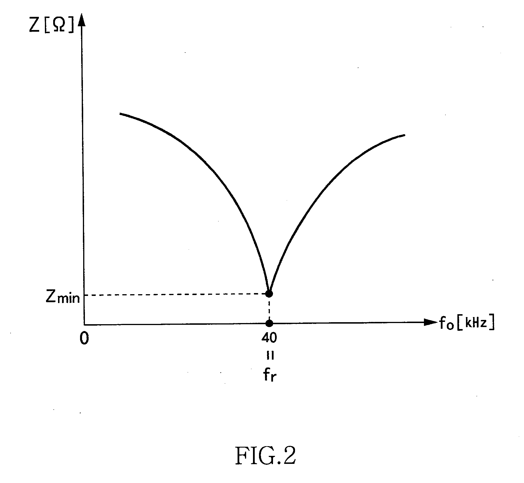
e frequency and resonance frequency coincide with each other;

[0039]FIG. 10 is a time chart observed when the level of a T2 signal is made to rise in a state of FIG. 9;

[0040]FIG. 11 is a time chart observed when a predetermined time period has elapsed from a state illustrated in FIG. 10;

[0041]FIG. 12 is a graph illustrating a relationship between output power and phase difference;

[0042]FIG. 13 is a graph illustrating a relationship between drive frequency and output power;

[0043]FIG. 14 is a graph illustrating a relationship between output power efficiency and drive frequency in a state where the resonance frequency is changed;

[0044]FIG. 15 is a side view of a table and a table lamp realized by using the wireless power transmission system;

[0045]FIG. 16 is a view illustrating the outer appearances of the table and table lamp; and

[0046]FIG. 17 is a system configuration view of a modification of the wireless power transmission system.

DETAILED DESCRIPTION OF THE EMBODIMENTS

[0047]A preferr...


PUM


Abstract

Power is fed from a feeding coil L2 to a receiving coil L3 by magnetic resonance. A VCO alternately turns ON/OFF switching transistors Q1 and Q2 at a drive frequency fo, whereby AC current is fed to the feeding coil L2, and then the AC current is fed from the feeding coil L2 to the receiving coil L3. A phase detection circuit detects a phase difference between the current phase and voltage phase, and the VCO adjusts the drive frequency fo such that the phase difference becomes zero. In a current phase detection circuit and a voltage phase detection circuit, detection values of the current and voltage phases can be changed, respectively and intentionally.

Description

BACKGROUND OF THE INVENTION[0001]1. Field of the Invention[0002]The present invention relates to a wireless AC power feeding and, more particularly, to power control thereof.[0003]2. Description of Related Art[0004]A wireless power feeding technique of feeding power without a power cord is now attracting attention. The current wireless power feeding technique is roughly divided into three: (A) type utilizing electromagnetic induction (for short range); (B) type utilizing radio wave (for long range); and (C) type utilizing resonance phenomenon of magnetic field (for intermediate range).[0005]The type (A) utilizing electromagnetic induction has generally been employed in familiar home appliances such as an electric shaver; however, it can be effective only in a short range of several centimeters. The type (B) utilizing radio wave is available in a long range; however, it cannot feed big electric power. The type (C) utilizing resonance phenomenon is a comparatively new technique and is...

Claims


Application Information

Patent Timeline
Patent Type & Authority Applications(United States)
IPC IPC(8): H02J17/00H02M7/48
CPCH05B37/00H02J5/005H05B47/10H02J50/12
Inventor URANO, TAKASHI
Owner TDK CORPARATION
Why Eureka
Try Eureka