Control Device and Switching Power Supply

a control device and power supply technology, applied in the direction of power conversion systems, dc-dc conversion, instruments, etc., can solve the problems of source power or environment interference, electromagnetic interference (emi),

Inactive Publication Date: 2011-05-05
NOVATEK MICROELECTRONICS CORP
View PDF6 Cites 45 Cited by
  • Summary
  • Abstract
  • Description
  • Claims
  • Application Information

AI Technical Summary

Benefits of technology

[0007]It is therefore an objective of the present invention to provide a control device and switching power supply.
[0008]The present invention discloses a control device for a switching power supply. The switching power supply includes a transformer, for supplying a direct current (DC) electric power. The control device includes an frequency-hopping oscillator, for generating an oscillating signal and an indication signal, a frequency of the oscillating signal switched among a plurality of frequencies, the indication signal indicating a variation condition of the frequency, an SR flip flop, including a set terminal coupled to the oscillating signal of the frequency-hopping oscillator, a reset terminal coupled to a comparison result, and an output terminal, for outputting a driving signal via the output terminal according to signals of the set terminal and the reset terminal, so as to control a primary winding of the transformer, a comparator, including a first signal terminal for receiving a current sense signal of the primary winding, a second signal terminal for receiving a subtraction result, and a third signal terminal coupled to the reset terminal of the SR flip flop, for comparing signals of the first signal terminal and the second signal terminal, and outputting the comparison result to the reset terminal of the SR flip flop via the third signal terminal, a ramp generator, for generating a ramp signal with a time-varying slope according to the indication signal, and a subtraction unit, for performing a subtraction operation on a feedback signal related to the DC electric power and the ramp signal, to generate the subtr

Problems solved by technology

In fact, there are some unideal characteristics of the flyback switching power supply 10 leading to eff

Method used


Image

  • Control Device and Switching Power Supply
  • Control Device and Switching Power Supply
  • Control Device and Switching Power Supply

Examples


Embodiment Construction

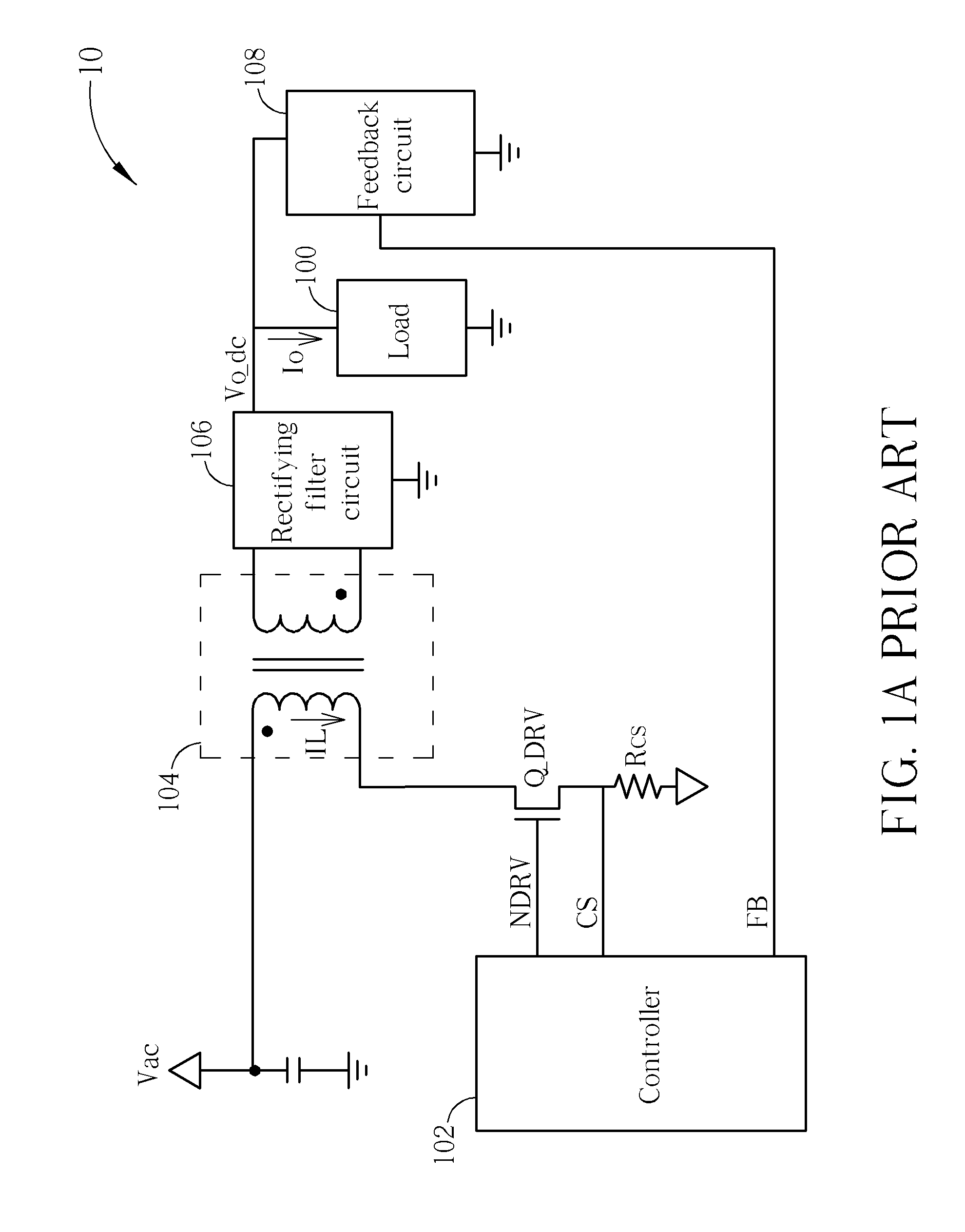
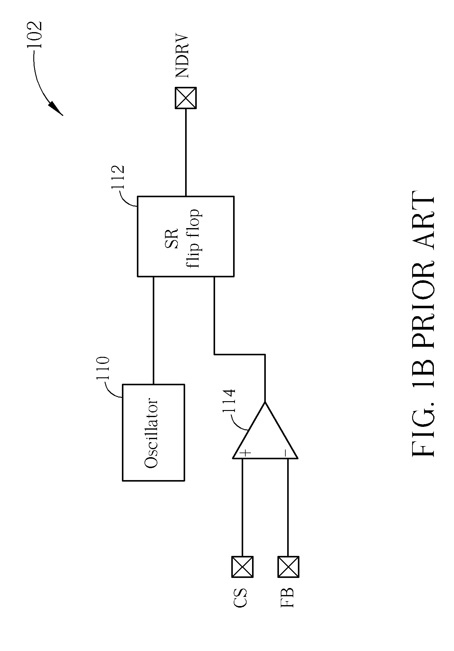
[0020]Generally, Electromagnetic Interference (EMI) energy is often concentrated within certain frequency bands under the same operating environment. Thus, in order to reduce unideal effects due to EMI, one improving method is to provide different oscillating frequencies, so as to adjust an operating frequency of the whole system, for reducing EMI effect. Please refer to FIG. 3, which is a schematic diagram of related signals when the flyback switching power supply 10 operates at two distinct frequencies. In order to clarify a variation condition of the inductive current IL, an equivalent current of the feedback signal FB (i.e. FB / Rcs) is denoted by a signal FB_eq in FIG. 3. In other words, FIG. 3 can be seen as an illustration that the feedback signal FB and the current sense signal CS are divided by the resistor Rcs. As can be seen from FIG. 3, the oscillator 110 increases an frequency from f1 to f2 at time t_FHP, while reduces amplitude of the feedback signal FB properly, such th...


PUM


Abstract

A control device for a switching power supply includes an frequency-hopping oscillator for generating an oscillating signal and an indication signal, an SR flip flop for outputting a driving signal according to the oscillating signal and the indication signal, to control a primary winding of a transformer of the switching power supply, a comparator for comparing a current sense signal of the primary winding and a subtraction result, to output the comparison result to the SR flip flop, a ramp generator for generating ramp signals with time-varying slopes, and a subtraction unit for performing a subtraction operation on a feedback signal and the ramp signals, to generate the subtraction result for the comparator.

Description

BACKGROUND OF THE INVENTION[0001]1. Field of the Invention[0002]The present invention relates to a control device and switching power supply, and more particularly, to a control device and switching power supply capable of enhancing anti-interference ability and effectively maintaining system stability.[0003]2. Description of the Prior Art[0004]Flyback switching power supplies have merits such as high efficiency, low loss, small size and light weight, and thus have been widely used as power conversion devices in a variety of electronic products. Please refer to FIG. 1A, which is a schematic diagram of a conventional flyback switching power supply 10. The flyback switching power supply 10 is utilized for converting an alternating current (AC) input power Vac into a direct current (DC) electric power Vo_dc, and supplying or driving a load 100. The flyback switching power supply 10 mainly includes a controller 102, a transformer 104, a rectifying filter circuit 106, a feedback circuit ...

Claims


Application Information

Patent Timeline
IPC IPC(8): G05F3/08
CPCH02M3/33507H02M1/44
Inventor CHENG, LAN-SHANHSIEH, CHIH-YUAN
Owner NOVATEK MICROELECTRONICS CORP
Why Eureka
Try Eureka