Apparatus and method for correcting duty cycle of clock signal

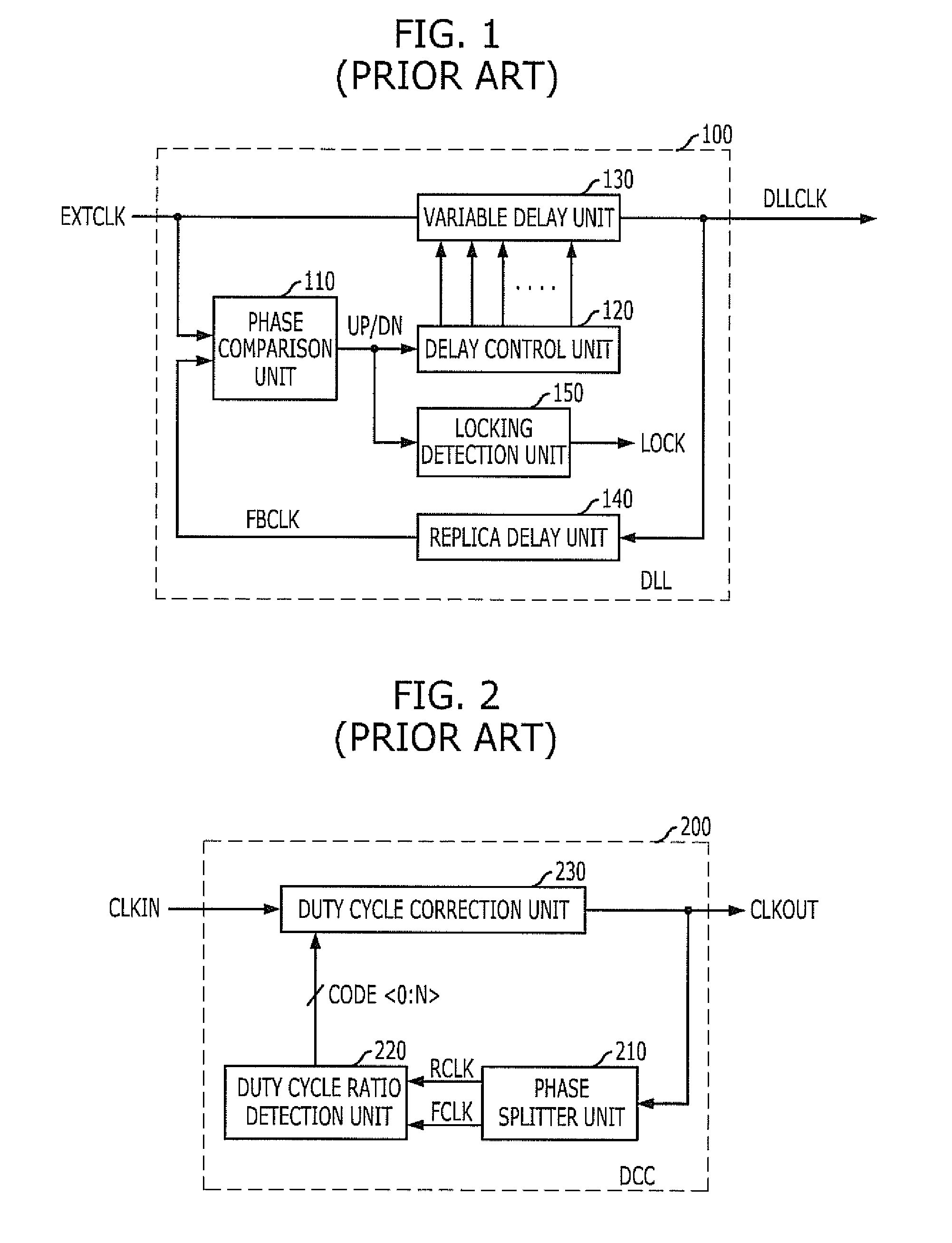
a technology of duty cycle and clock signal, which is applied in the direction of pulse manipulation, pulse technique, instruments, etc., can solve the problems of not being able to correct the change in the duty cycle caused by the variable delay unit b>130/b>, and the clock signal is often delayed, so as to achieve the effect of not increasing the chip size or minimally increasing the

Active Publication Date: 2011-05-05
SK HYNIX INC
View PDF8 Cites 53 Cited by
  • Summary
  • Abstract
  • Description
  • Claims
  • Application Information

AI Technical Summary

Problems solved by technology

While the clock signal is used inside of the systems and circuits, the clock signal is often delayed.
However, the change in the duty cycle caused by the variable delay unit 130 is not corrected.

Method used


Image

  • Apparatus and method for correcting duty cycle of clock signal
  • Apparatus and method for correcting duty cycle of clock signal
  • Apparatus and method for correcting duty cycle of clock signal

Examples


Embodiment Construction

[0024]Exemplary embodiments of the present invention will be described below in more detail with reference to the accompanying drawings. The present invention may, however, be embodied in different forms and should not be construed as being limited to the embodiments set forth herein. Rather, these embodiments are provided so that this disclosure will be thorough and complete, and will fully convey the scope of the present invention to those skilled in the art. Throughout the disclosure, like reference numerals refer to like parts throughout the various figures and embodiments of the present invention.

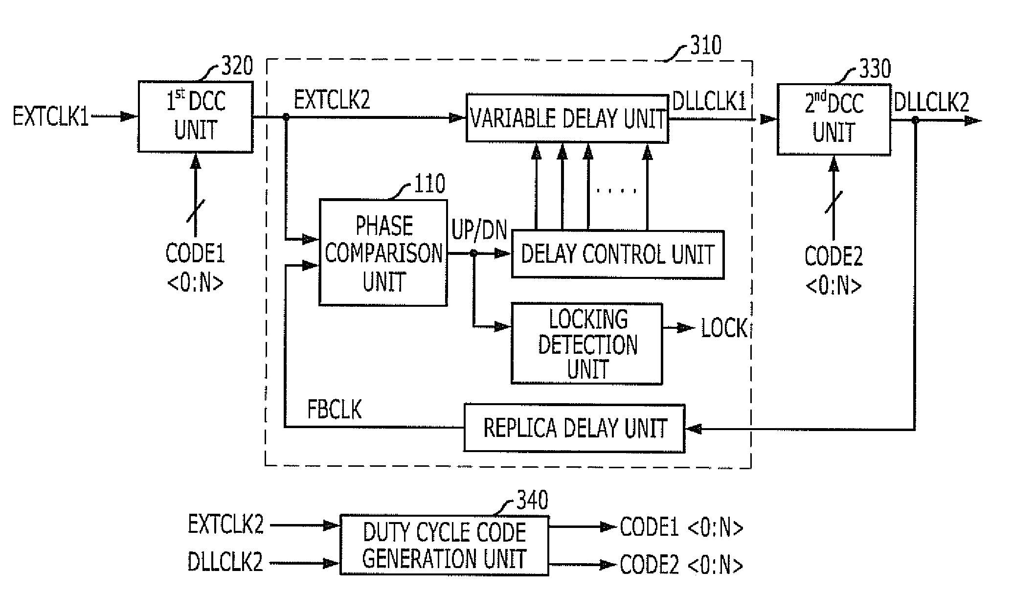
[0025]FIG. 3 is a block diagram illustrating a clock correction circuit in accordance with an embodiment of the present invention. The clock correction circuit includes a delay locked loop (DLL) 310, first and second duty cycle correction (DCC) units 320 and 330, and a duty cycle code generation unit 340. The first DCC unit 320 corrects a duty cycle of a first external clock signal EXT...


PUM


Abstract

A clock correction circuit includes a delay locked loop (DLL) configured to delay an external clock signal and to generate an internal clock signal, a first duty cycle correction (DCC) unit configured to correct a duty cycle of the external clock signal in response to a first duty cycle code, a second DCC unit configured to correct a duty cycle of the internal clock signal in response to a second duty cycle code, and a duty cycle code generation unit configured to select an output of from outputs of the first and second DCC Units and to generate the first and second duty cycle codes by detecting a duty cycle ratio of the selected output.

Description

CROSS-REFERENCE TO RELATED APPLICATION[0001]The present application claims priority of Korean Patent Application No. 10-2009-0104624, filed on Oct. 30, 2009, which is incorporated herein by reference in its entirety.BACKGROUND OF THE INVENTION[0002]Exemplary embodiments of the present invention relate to an apparatus for correcting a duty cycle of a clock signal.[0003]Clock signals are widely used for adjusting an operational timing in various systems and circuits. While the clock signal is used inside of the systems and circuits, the clock signal is often delayed. It is important to correct the delay for securing a reliable operation. A delay locked loop (DLL) is generally used for compensating the delay of the clock signal.[0004]FIG. 1 is a block diagram illustrating a conventional DLL.[0005]The conventional DLL 100 includes a phase comparison unit 110, a delay control unit 120, a variable delay unit 130, a replica delay unit 140, and a locking detection unit 150.[0006]The replica...

Claims


Application Information

Patent Timeline
Patent Type & Authority Applications(United States)
IPC IPC(8): H03K5/04
CPCG11C7/22G11C7/222H03L7/0816H03L7/0814H03K5/1565G11C8/00
Inventor SHIN, SEOK-BO
Owner SK HYNIX INC
Why Eureka
Try Eureka