
Antenna apparatus

a technology of antenna apparatus and antenna earthing, which is applied in the direction of resonant antennas, antenna earthings, elongated active element feeds, etc., can solve the problems that small wireless communication apparatuses using dipole antennas may not meet consumer requirements, and achieve the effect of improving the efficiency of the antenna apparatus

Active Publication Date: 2011-05-05
MEDIATEK INC
View PDF2 Cites 0 Cited by
  • Summary
  • Abstract
  • Description
  • Claims
  • Application Information

AI Technical Summary

Benefits of technology

[0010]The present invention discloses an antenna apparatus, which uses an extending layer such that the antenna apparatus exhibits characteristics of a dipole antenna. Accordingly, the efficiency of the antenna apparatus is improved.

Problems solved by technology

Conventional monopole antennas in a USB application inherit disadvantages of typical monopole antennas.
On the other hand, small wireless communication apparatuses using dipole antennas may not meet consumer requirements since dipole antennas require much greater size.

Method used


Image

  • Antenna apparatus
  • Antenna apparatus
  • Antenna apparatus

Examples


Embodiment Construction

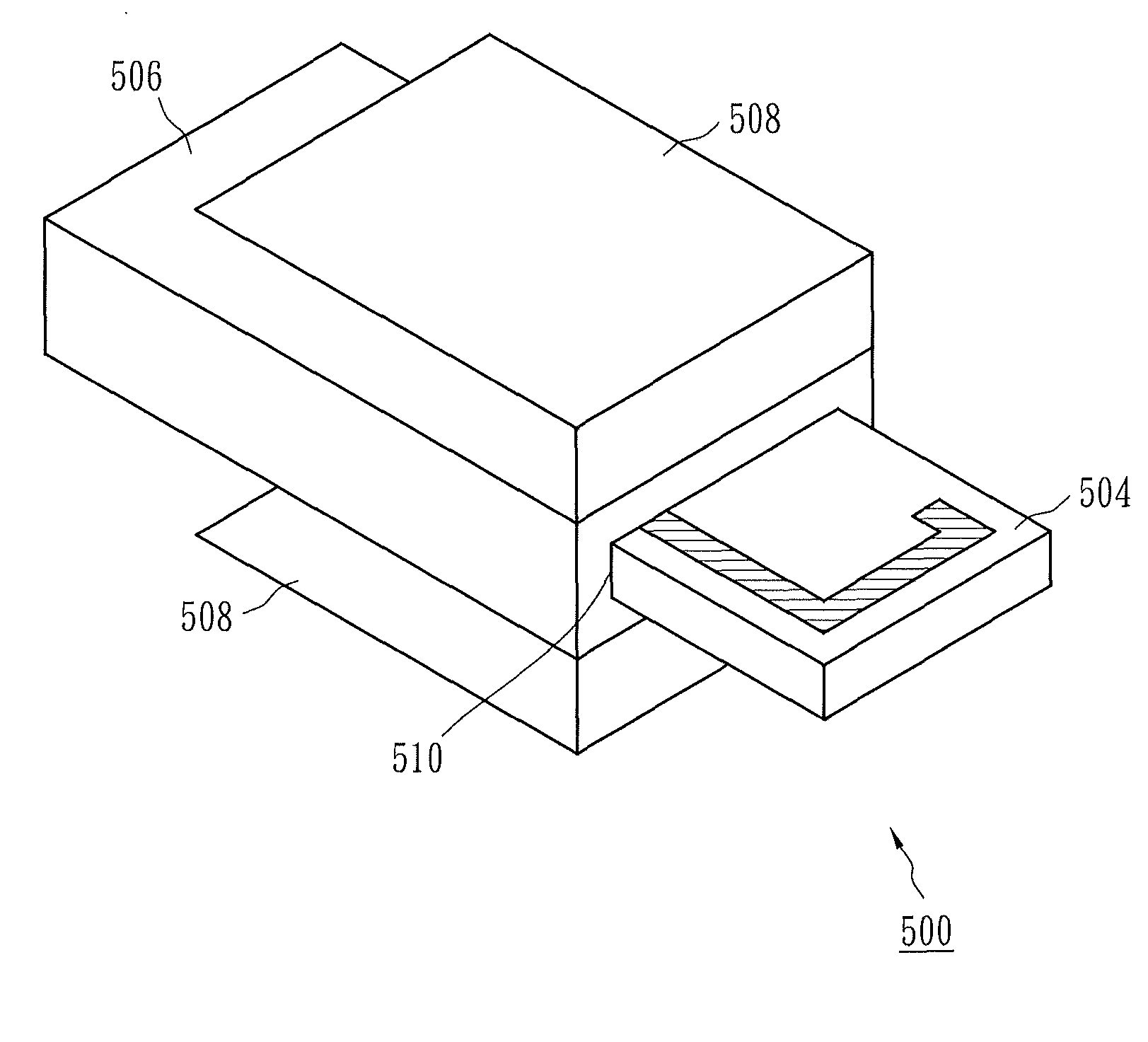
[0023]FIG. 5 shows a side view of an antenna apparatus according to one embodiment of the present invention. As shown in FIG. 5, the antenna apparatus 500 comprises a printed circuit board 502, an antenna end 504, an electromagnetic shielding box 506 and an extending layer 508. The printed circuit board 502 comprises a radio frequency circuit of the antenna apparatus 500. The antenna end 504 comprises a bent metal antenna, and is connected to the printed circuit board 502. The electromagnetic shielding box 506 covers the printed circuit board 502 to provide noise suppression for the antenna apparatus 500. The extending layer 508 is composed of electrical conducting material, and extends outward from a feed point 510 of the electromagnetic shielding box 506.

[0024]The architecture of the combination of the printed circuit board 502, the antenna end 504 and the electromagnetic shielding box 506 is similar to that of a monopole antenna. In other words, the antenna end 504 serves as a si...


PUM


Abstract

An antenna apparatus comprises a planar monopole antenna device and an extending layer. The planar monopole antenna device includes an electromagnetic shielding box. The extending layer is composed of electric conducting material and extends outward from a feed point of the electromagnetic shielding box.

Description

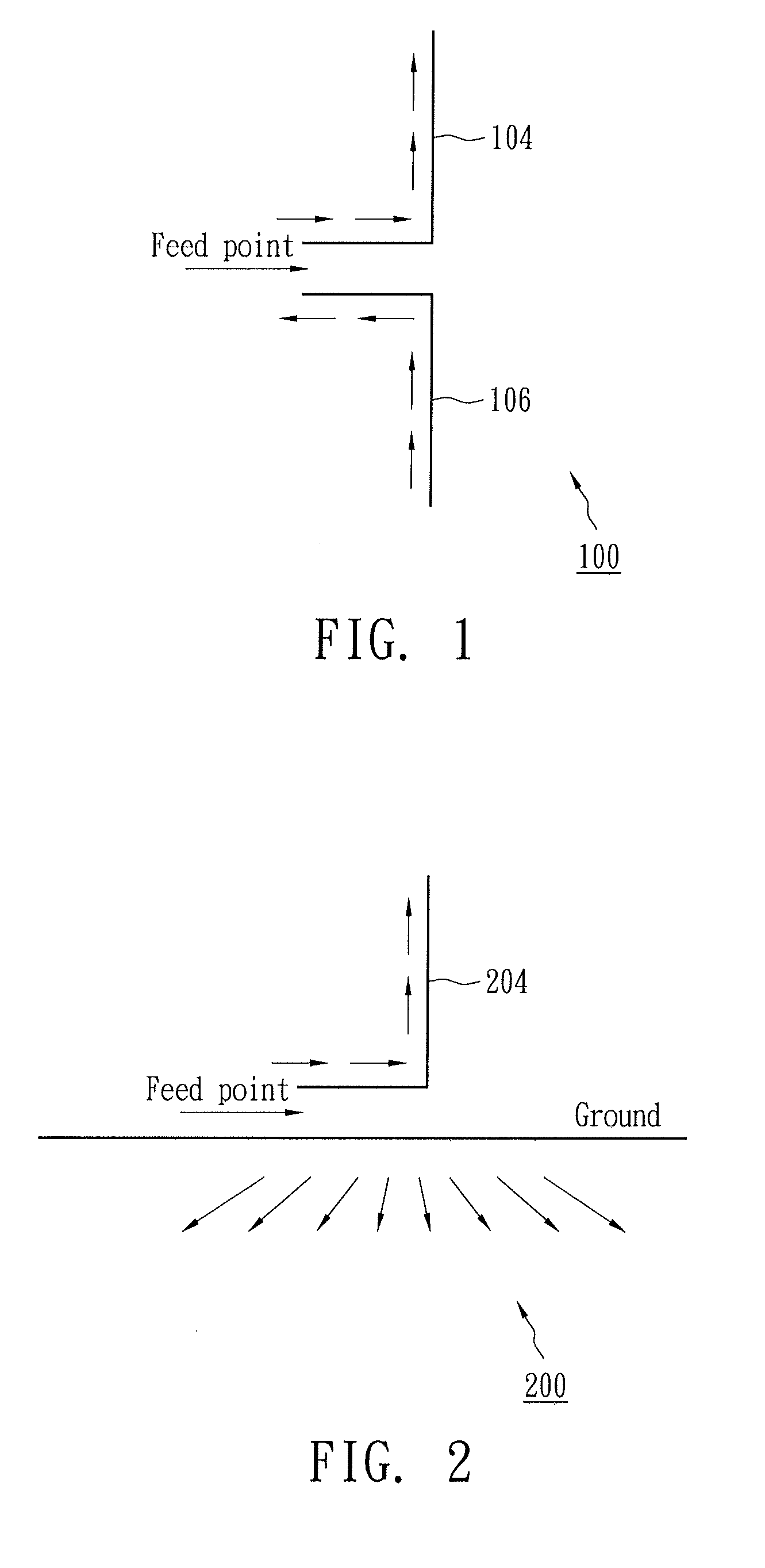
BACKGROUND OF THE INVENTION[0001]1. Field of the Invention[0002]The present invention relates to an antenna apparatus, and more particularly, to an antenna apparatus including an electromagnetic shielding box.[0003]2. Description of the Related Art[0004]In a wireless communication system, an antenna apparatus is needed to transmit and receive electromagnetic wave carrying signals. Dipole antenna architecture is one of the basic antenna architectures and originated from an invention in the 19th century. FIG. 1 shows the architecture of a dipole antenna. As shown in FIG. 1, the dipole antenna 100 comprises two antenna ends extending outward from a feed point. A first antenna end 104 serves as a signal source of the dipole antenna 100. A second antenna end 106 serves as a ground of the dipole antenna 100. The current directions of the first antenna end 104 and the second antenna end 106 are shown in FIG. 1, wherein the current level reaches the highest level at the feed point, and reac...

Claims


Application Information

Patent Timeline
Patent Type & Authority Applications(United States)
IPC IPC(8): H01Q1/52H01Q1/38H01Q1/48
CPCH01Q9/42H01Q1/38
Inventor LIN, JUNN YICHEN, XIN CHANG
Owner MEDIATEK INC
Learn More