
Display device

a technology of display device and display function, which is applied in the field of display device, can solve the problems of image reading device of patent literature 2, but cannot have image sensing function and display function simultaneously

Inactive Publication Date: 2011-05-05
SHARP KK
View PDF3 Cites 32 Cited by
  • Summary
  • Abstract
  • Description
  • Claims
  • Application Information

AI Technical Summary

Benefits of technology

[0016]Thus, in a case where an image sensing object is provided with a decoration (for example, a print) which has (i) a low reflectance for visible light and (ii) a high reflectance for non-visible light, the display device can selectively obtain, when sensing an image of a single image sensing object, a visible light image (visible image) and a non-visible light image (invisible image) from the image sensing object by controlling a light transmittance of the display panel. The light transmittance of the display panel can be flexibly changed by changing a property (for example, a color and a pattern) of an image to be displayed on the display panel. Further, by partially changing a display state of the display panel, it is possible to, for example, emit non-visible light from only a part of the display panel toward the image sensing object.
[0036]As described above, the display device of the present invention includes an irradiation light control section which controls the ratio between visible light and non-visible light, both emitted to an image sensing object, by changing the display state of the display panel. The display device can thus (i) simultaneously achieve a display function and an image sensing function and (ii) sense an image with use of at least non-visible light.

Problems solved by technology

The image reading device of Patent Literature 2, however, cannot simultaneously have a display function and an image sensing function.

Method used


Image

  • Display device
  • Display device
  • Display device

Examples


Embodiment Construction

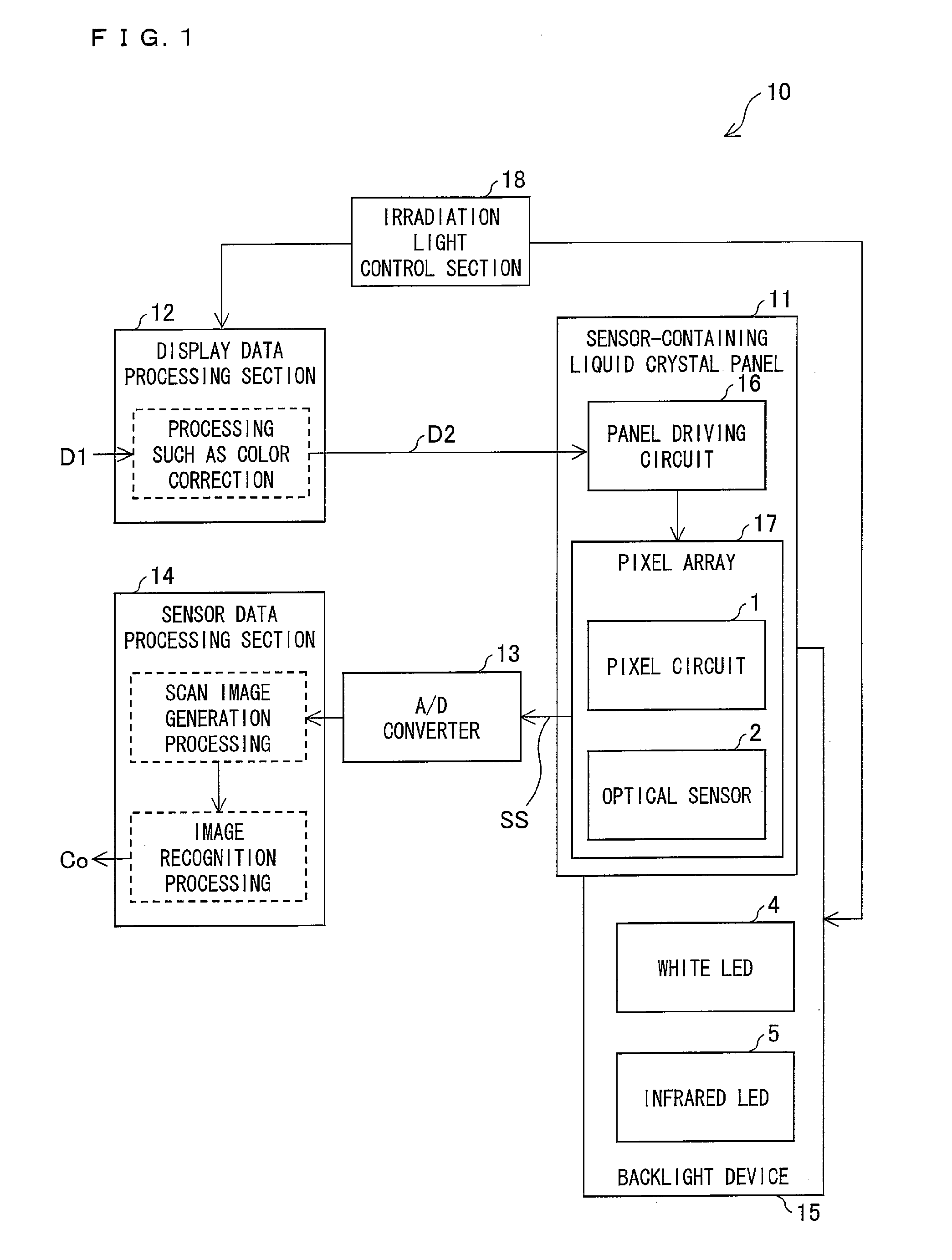
[0055]An embodiment of the present invention will be described below with reference to FIGS. 1 through 17.

[0056](Configuration of Liquid Crystal Display Device 10)

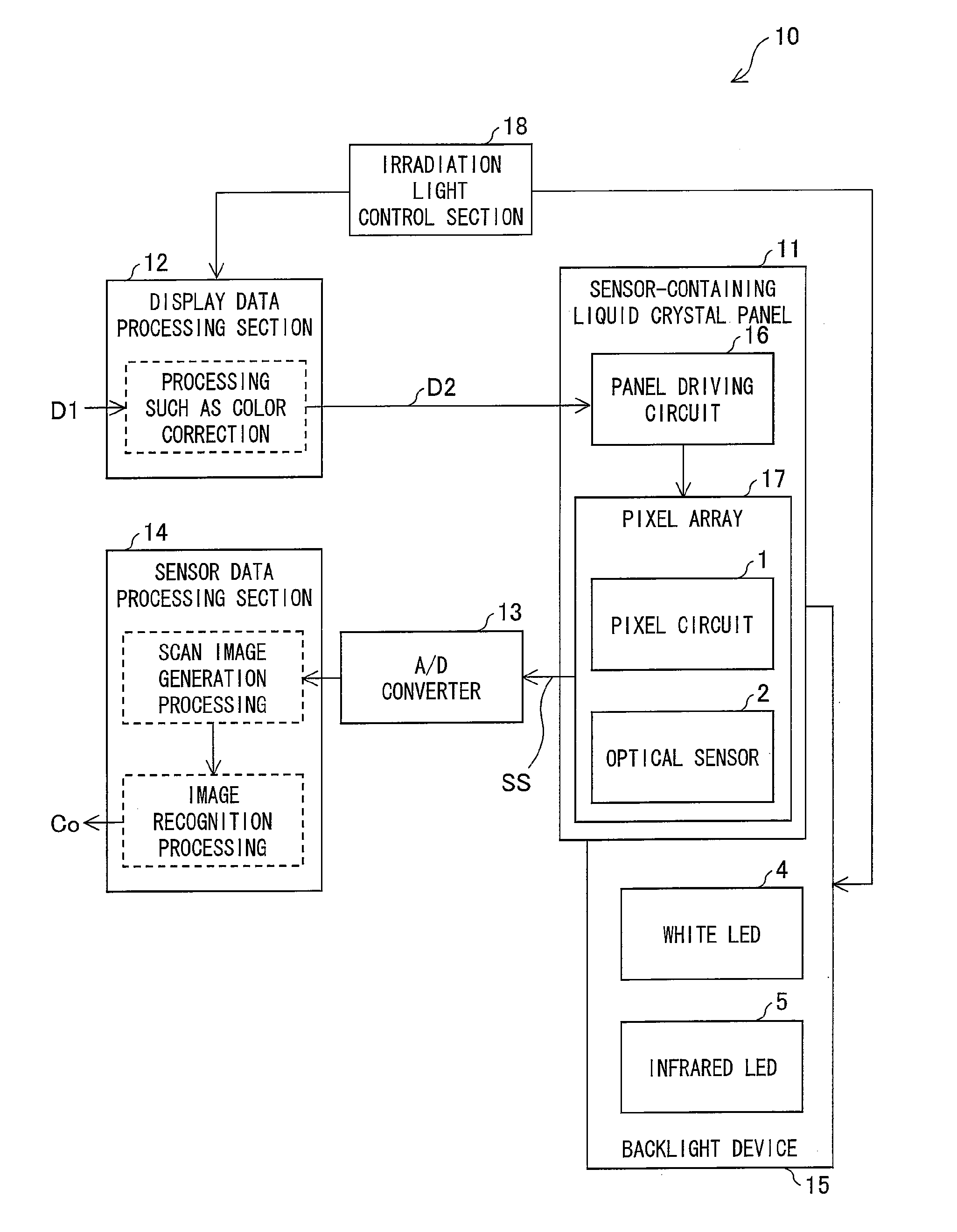
[0057]FIG. 1 is a block diagram illustrating an arrangement of a liquid crystal display device 10 in accordance with an embodiment of the present invention. The liquid crystal display device 10 of FIG. 1 includes: a sensor-containing liquid crystal panel 11; a display data processing section 12; an A / D converter 13; an image sensing processing section (sensor data processing section) 14; a backlight device 15; and an irradiation light control section 18. The sensor-containing liquid crystal panel 11 (hereinafter referred to as “liquid crystal panel 11) includes panel driving circuits 16 and a pixel array 17. The pixel array 17 includes (i) a plurality of pixel circuits 1 and (ii) a plurality of optical sensors 2, both of which are aligned two-dimensionally.

[0058]The liquid crystal display device 10 receives display data D1...


PUM


Abstract

A liquid crystal display device (10) is a liquid crystal display device (10) having a function of sensing an image of an image sensing object, the liquid crystal display device (10) comprising: a liquid crystal panel (11) which transmits light that has entered the liquid crystal panel (11) and which has a transmittance variable for the light; a backlight device (15) which emits, to the liquid crystal panel (11), both visible light and non-visible light; and an optical sensor (2) which is provided in the liquid crystal panel (11) and which receives at least infrared light (non-visible light) that enters the liquid crystal panel (11), the liquid crystal display device (10) adjusting a ratio between the visible light and the non-visible light, both of which are emitted to an image sensing object, so as to sense an image of the image sensing object with use of at least the non-visible light. The liquid crystal display device (10) can thus (i) simultaneously achieve a display function and an image sensing function and (ii) sense an image with use of at least non-visible light.

Description

TECHNICAL FIELD[0001]The present invention relates to a display device which has a function of sensing an image of an image sensing object with use of at least non-visible light.BACKGROUND ART[0002]Growing awareness about security has conventionally led to implementation of a measure of printing, on a valuable printed material (for example, a bank note and a securities certificate), not only a visible image but also an invisible image which is perceivable only when irradiated with non-visible light.[0003]For example, a visible light image is printed on a printed material with an ink which reflects visible light, and an infrared light image is further printed on the printed material with an ink which reflects infrared light. The human eye can, when seeing such a printed material, perceive the visible light image, but cannot perceive the infrared light image. Such a hidden infrared light image is perceivable only when sensed with use of infrared light. Thus, even in a case where the h...

Claims


Application Information

Patent Timeline
Patent Type & Authority Applications(United States)
IPC IPC(8): G09G3/36G09G5/10
CPCG02F1/13338G09G3/3406G09G2360/144G09G2320/0626G09G2340/0435G09G2320/0242
Inventor FUJIOKA, AKIZUMIYANAGI, TOSHIHIRO
Owner SHARP KK
Learn More