
Microscope objective lens
a technology of objective lens and microscope, which is applied in the field of microscope objective lens, can solve the problems of inconvenient cost of conventional microscope objective lens, and achieve the effects of sufficient visual field range, favorable correction, and sufficient correction of chromatic aberration
- Summary
- Abstract
- Description
- Claims
- Application Information
AI Technical Summary
Benefits of technology
Problems solved by technology
Method used
Image

Examples
first embodiment
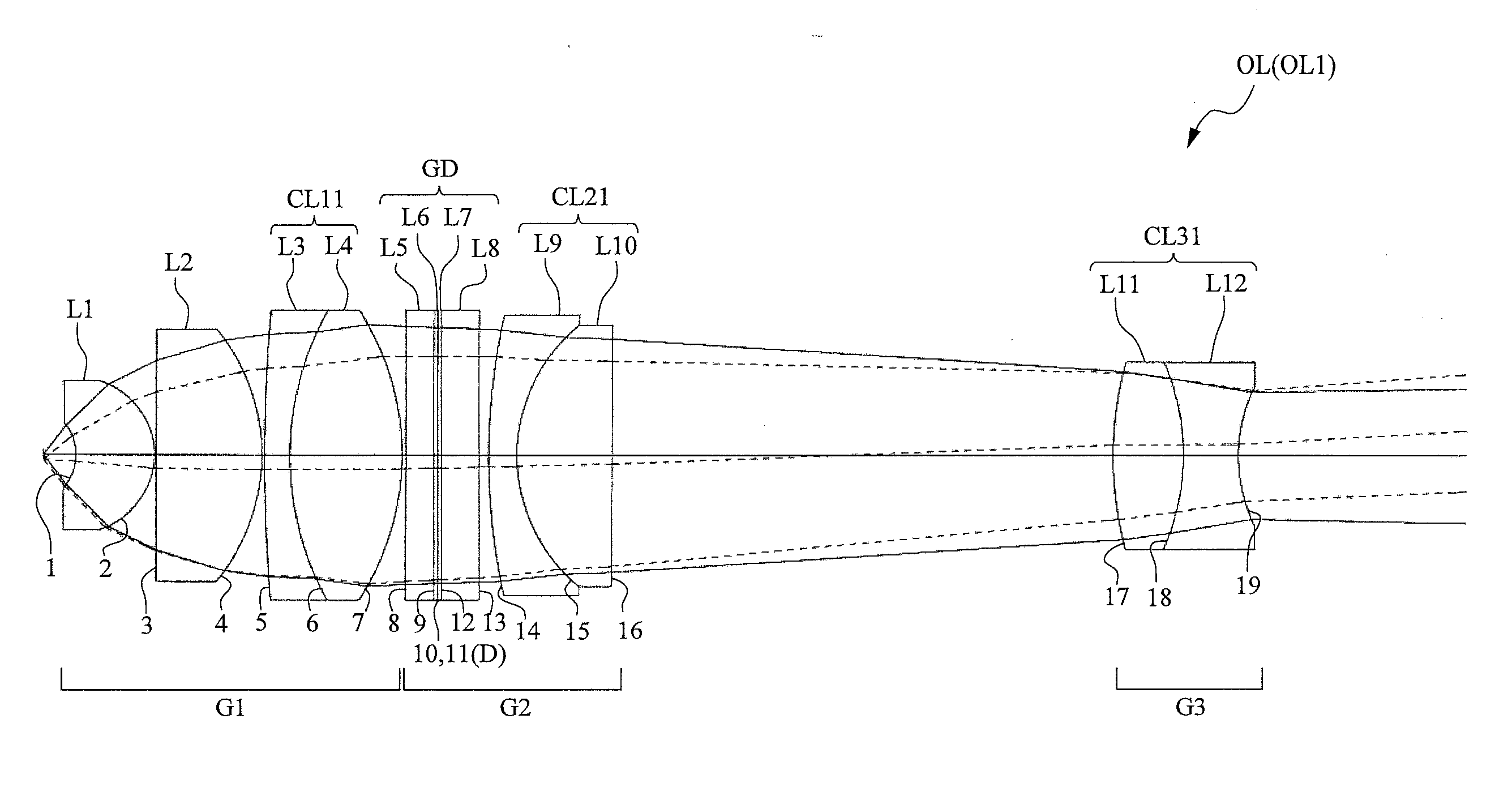
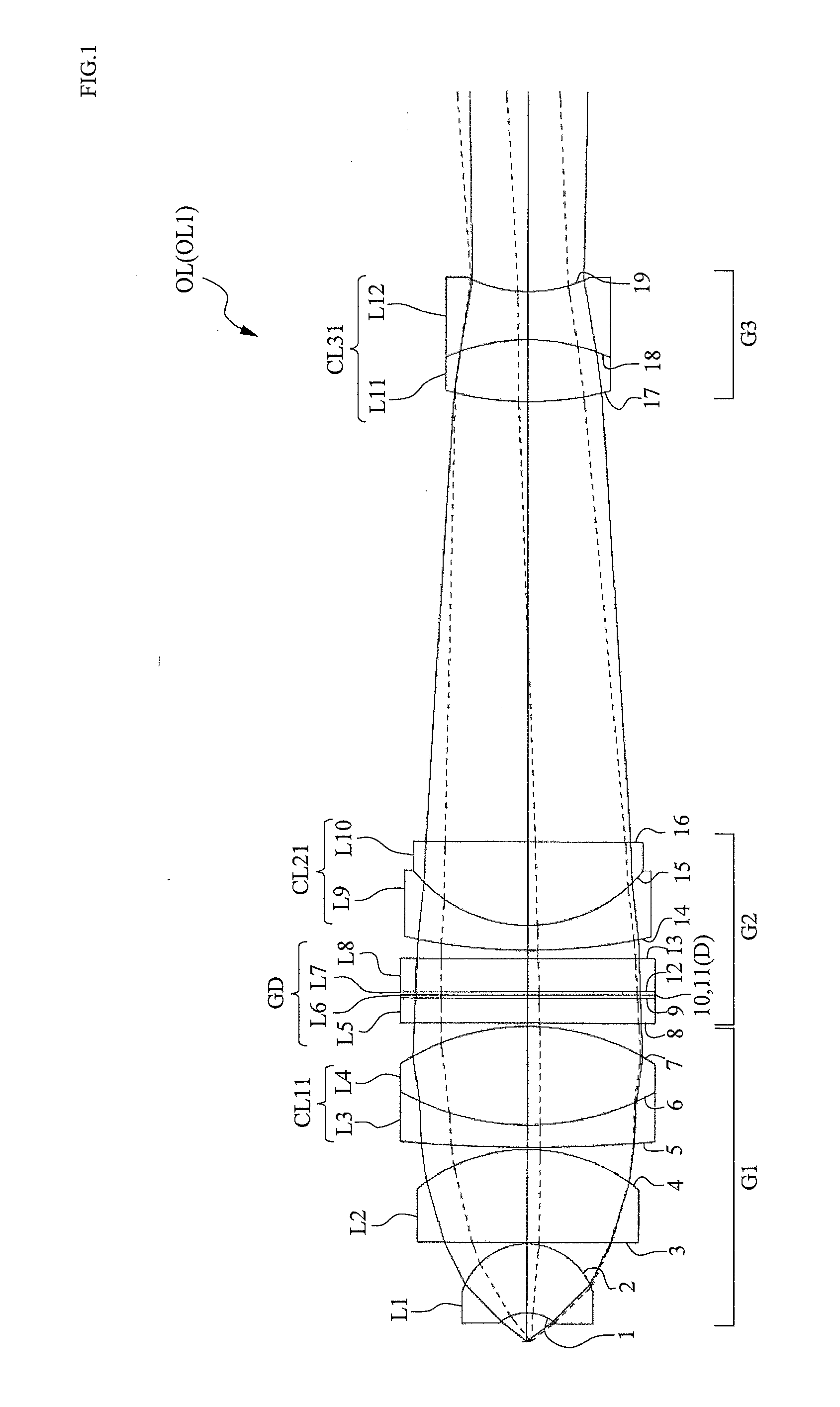
[0051]Hereinafter, preferred embodiments of the present invention will be described with reference to the drawings. First, a high-magnification microscope objective lens will be described. FIG. 1 illustrates a microscope objective lens OL according to a first embodiment comprising, in order from the object side, a first lens group G1 having a positive refractive power, a second lens group G2, and a third lens group G3 having a negative refractive power.
[0052]In the microscope objective lens OL described above, the first lens group G1 is a lens group for approximating a divergent light bundle from an object to a parallel light bundle. To this end, the first lens group G1 is configured so as to include a positive lens component (for example, a positive meniscus lens L1 illustrated in FIG. 1) having a lens surface with a negative refractive power, and at least one achromatizing lens component (a cemented lens CL11 illustrated in FIG. 1) that joins a positive lens and a negative lens. T...
second embodiment
[0072]Next, a case of a microscope objective lens having a long working distance will be described. FIG. 11 illustrates a microscope objective lens OL according to a second embodiment comprising, in order from the object side, a first lens group G1 having a positive refractive power, a second lens group G2 having a positive refractive power, and a third lens group G3 having a negative refractive power.
[0073]In the microscope objective lens OL described above, the first lens group G1 is a lens group for approximating a divergent light bundle from an object to a parallel light bundle. To this end, the first lens group G1 is configured so as to include a positive lens component (for example, a positive meniscus lens L1 illustrated in FIG. 11) having a lens surface with a negative refractive power, and at least one achromatizing lens component (a cemented lens CL11 illustrated in FIG. 11) that joins a positive lens and a negative lens. The positive lens component may be configured using...
third embodiment
[0092]Finally, a low-magnification microscope objective lens will be described. FIG. 19 illustrates a microscope objective lens OL according to a third embodiment comprising, in order from the object side, a first lens group G1 having a positive refractive power, a second lens group G2, and a third lens group G3 having a negative refractive power.
[0093]In the microscope objective lens OL described above, the first lens group G1 is a lens group for approximating a divergent light bundle from an object to a parallel light bundle. To this end, the first lens group G1 is configured so as to include a positive lens component (for example, a positive meniscus lens L1 illustrated in FIG. 19) positioned nearest to the object side and having a lens surface with a negative refractive power. The positive lens component may be configured using a single lens or a cemented lens. If r denotes a curvature radius of the lens surface (for example, a first surface illustrated in FIG. 19) having a nega...
PUM
 Abstract
Description
Claims
Application Information