

Imaging lens
a technology of imaging lenses and lenses, applied in the field of imaging lenses, can solve the problems of difficult to secure difficult to achieve good overall image optical performance, and unsuitable glass materials for mass production, etc., and achieves sufficient brightness, wide field of view, and favorable correction of various aberrations.
- Summary
- Abstract
- Description
- Claims
- Application Information
AI Technical Summary
Benefits of technology
Problems solved by technology
Method used
Image

Examples
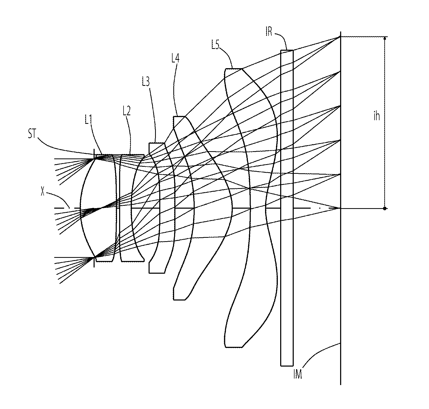
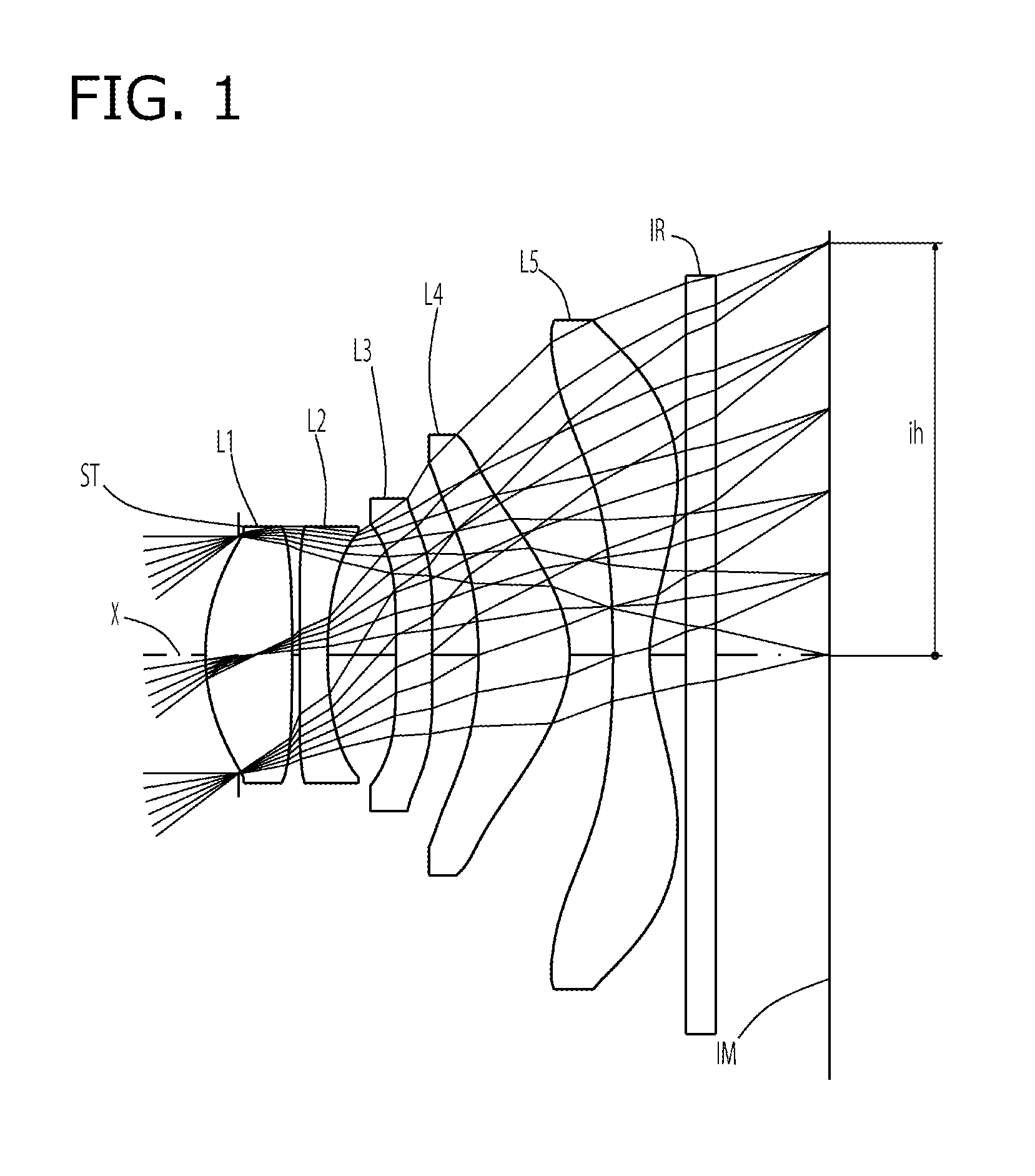
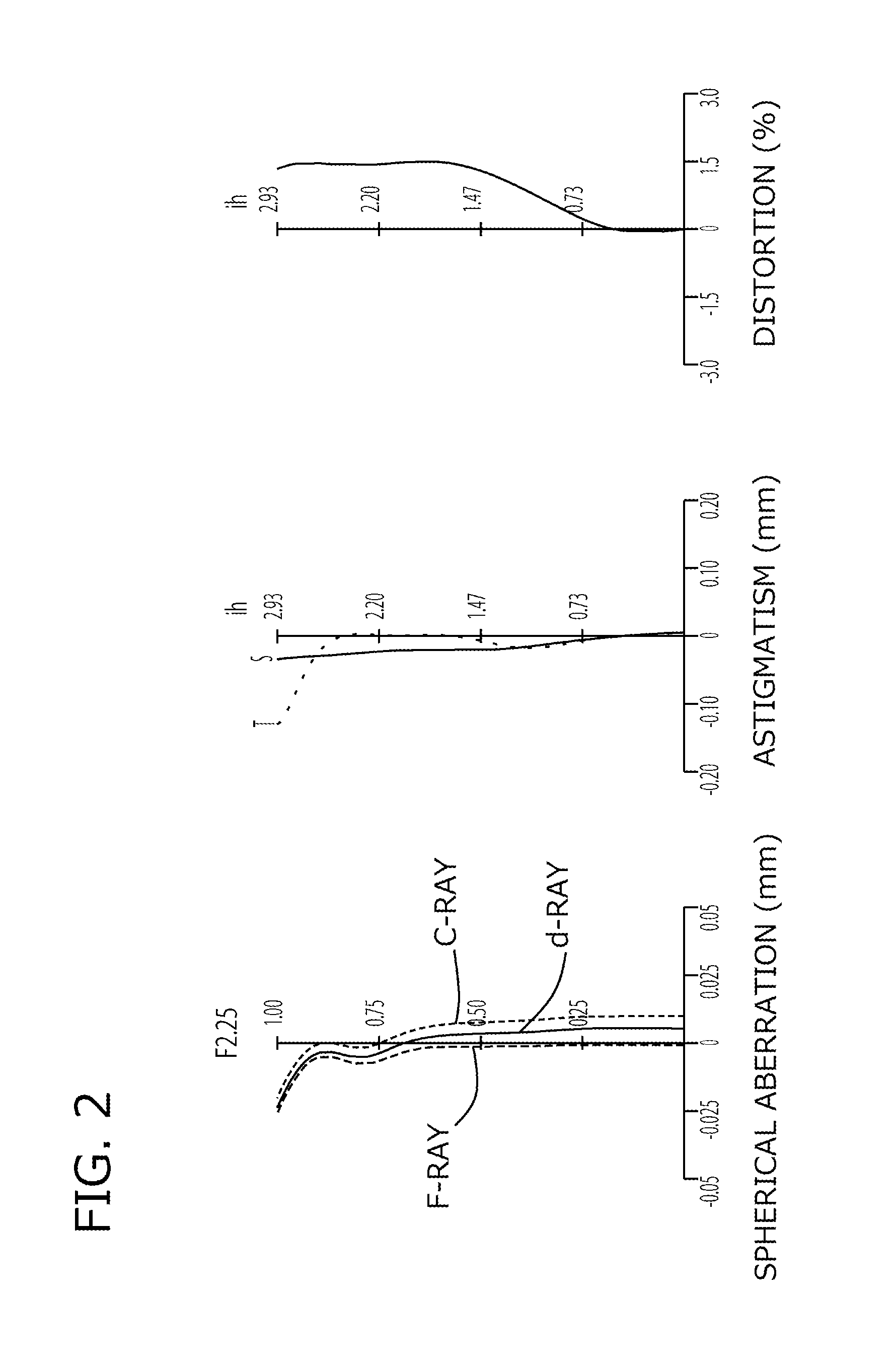
example 1
[0104]The basic lens data is shown below in Table 1.
TABLE 1Example 1in mmf = 3.80Fno = 2.25ω(°) = 37.3ih = 2.93TLA = 4.38b f = 1.22Surface DataCurvatureSurfaceRefractiveAbbeSurface No. iRadius rDistance dIndex NdNumber vd(Object Surface)InfinityInfinity 1 (Stop)Infinity−0.235 2*1.4320.6191.54455.57 3*−14.8740.052 4*−55.2940.2001.63523.97 5*2.7600.486 6*56.6490.2581.63523.97 7*16.2860.331 8*−2.8570.6511.54455.57 9*−0.8430.30910*−8.2840.2601.53556.1611*1.1580.26012Infinity0.2101.51764.2013Infinity0.811Image PlaneInfinityConstituent Lens DataLensStart SurfaceFocal Length122.43524−4.13436−36.089481.973510−1.883Aspheric Surface Data2nd Surface3rd Surface4th Surface5th Surface6th Surfacek−5.831E+000.000E+00−9.900E+015.796E+000.000E+00A42.334E−01−1.858E−022.375E−023.157E−03−2.182E−01A6−1.844E−015.007E−024.920E−029.589E−02−1.771E−01A81.105E−01−2.637E−011.488E−014.166E−023.096E−01A10−1.388E−023.515E−01−6.387E−01−2.691E−01−1.790E−01A12−6.347E−02−3.106E−018.081E−013.053E−011.122E−02A14−1.738E−...
example 2
[0108]The basic lens data is shown below in Table 2.
TABLE 2Example 2in mmf = 3.80Fno = 2.29ω(°) = 37.2ih = 2.93TLA = 4.38bf = 1.22Surface DataCurvatureSurfaceRefractiveAbbeSurface No. iRadius rDistance dIndex NdNumber vd(Object Surface)InfinityInfinity 1 (Stop)Infinity−0.254 2*1.4120.5641.54455.57 3*16.0030.042 4*19.1400.2571.63523.97 5*2.6150.342 6*5.1190.2941.54455.57 7*7.2920.506 8*−2.7470.5781.54455.57 9*−0.8440.20010*−12.7640.3931.54455.5711*1.0781640.30012Infinity0.2101.51764.1713Infinity0.767Image PlaneInfinityConstituent Lens DataLensStart SurfaceFocal Length122.80924−4.7993630.151482.022510−1.810Aspheric Surface Data2nd Surface3rd Surface4th Surface5th Surface6th Surfacek2.950E−010.000E+000.000E+00−2.182E+000.000E+00A4−1.546E−02−3.274E−01−3.997E−01−1.213E−01−2.305E−01A6−2.995E−031.234E+001.729E+006.981E−012.058E−02A82.229E−02−2.733E+00−3.935E+00−1.244E+00−1.007E−01A10−1.921E−014.183E+006.156E+001.659E+002.595E−01A123.577E−01−4.412E+00−6.307E+00−1.415E+00−4.124E−01A14−2.768E...
example 3
[0112]The basic lens data is shown below in Table 3.
TABLE 3Example 3in mmf = 3.80Fno = 2.25ω(°) = 37.3ih = 2.93TLA = 4.38bf = 1.22Surface DataCurvatureSurfaceRefractiveAbbeSurface No. iRadius rDistance dIndex NdNumber vd(Object Surface)InfinityInfinity 1 (Stop)Infinity−0.235 2*1.4150.6511.54455.57 3*−17.5970.039 4*−77.6420.2001.63523.97 5*2.6840.477 6*45.5600.2291.63523.97 7*17.4060.306 8*−2.7070.6671.54455.57 9*−0.8560.33610*−6.5850.2601.53556.1611*1.2600.26012Infinity0.2101.51764.2013Infinity0.813Image PlaneInfinityConstituent Lens DataLensStart SurfaceFocal Length122.43824−4.08236−44.502482.041510−1.956Aspheric Surface Data2nd Surface3rd Surface4th Surface5th Surface6th Surfacek−5.692E+000.000E+000.000E+005.541E+000.000E+00A42.441E−012.794E−024.981E−021.632E−03−2.213E−01A6−1.796E−011.067E−02−1.114E−028.473E−02−1.538E−01A81.266E−01−2.808E−011.041E−01−4.056E−032.846E−01A10−2.400E−033.587E−01−6.256E−01−2.373E−01−1.661E−01A12−6.365E−02−3.105E−018.081E−013.053E−011.128E−02A14−1.738E−0...
PUM
 Abstract
Description
Claims
Application Information