Microscope objective lens including a diffractive optical element

a technology of diffractive optical elements and microscopes, applied in the field of microscope objective lenses, can solve the problems of inconvenient cost of conventional microscope objective lenses, and achieve the effects of sufficient visual field range, favorable correction, and sufficient correction of chromatic aberration

Active Publication Date: 2015-02-17
NIKON CORP
View PDF17 Cites 7 Cited by
  • Summary
  • Abstract
  • Description
  • Claims
  • Application Information

AI Technical Summary

Benefits of technology

[0020]By configuring a microscope objective lens according to the present invention as described above, a microscope objective lens capable of sufficiently correcting chromatic aberration while offering a sufficient visual field range in which various aberrations are favorably corrected can be provided.

Problems solved by technology

Accordingly, conventional microscope objective lenses are inevitably expensive.

Method used


Image

  • Microscope objective lens including a diffractive optical element
  • Microscope objective lens including a diffractive optical element
  • Microscope objective lens including a diffractive optical element

Examples


first embodiment

[First Embodiment]

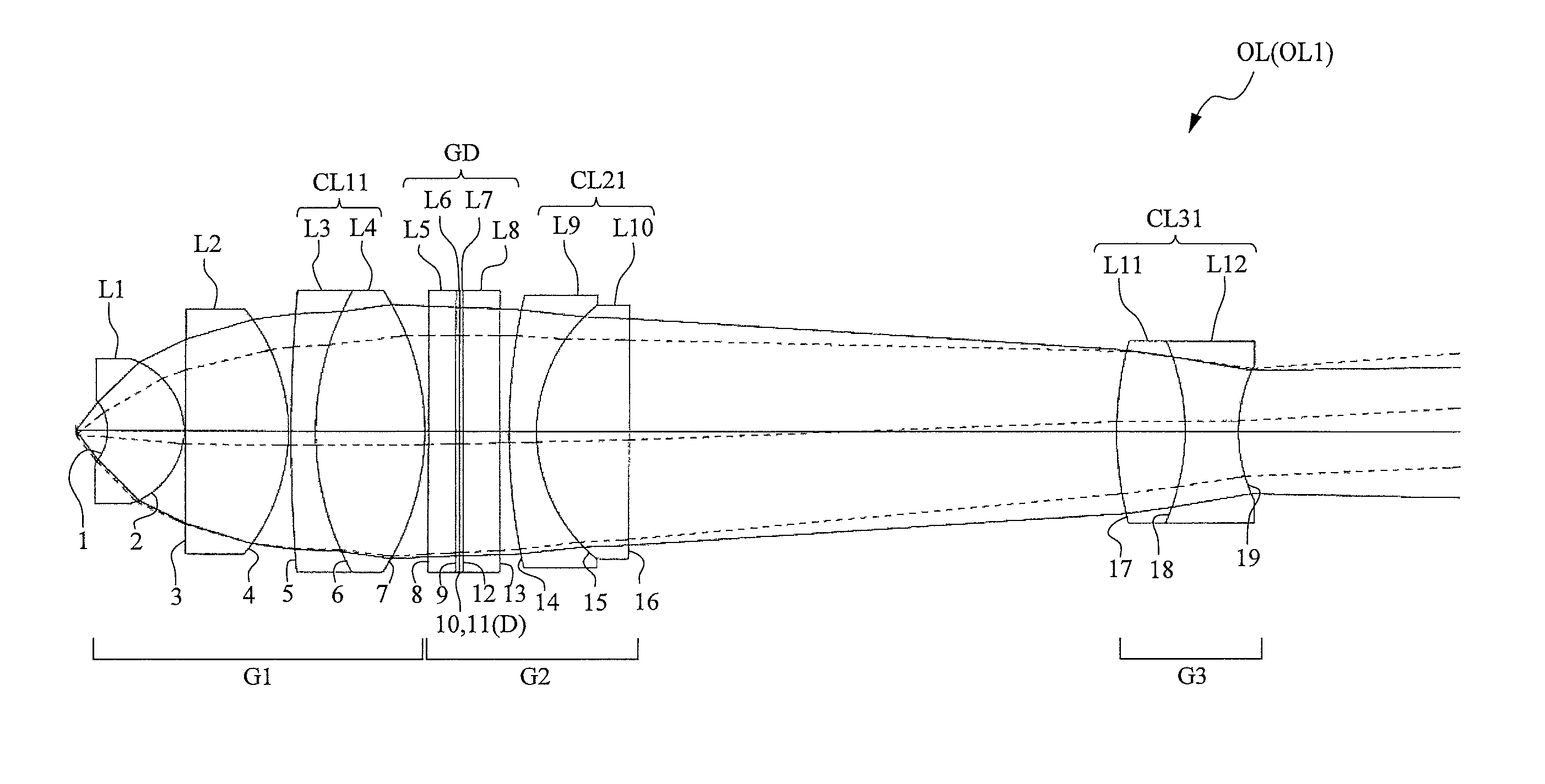
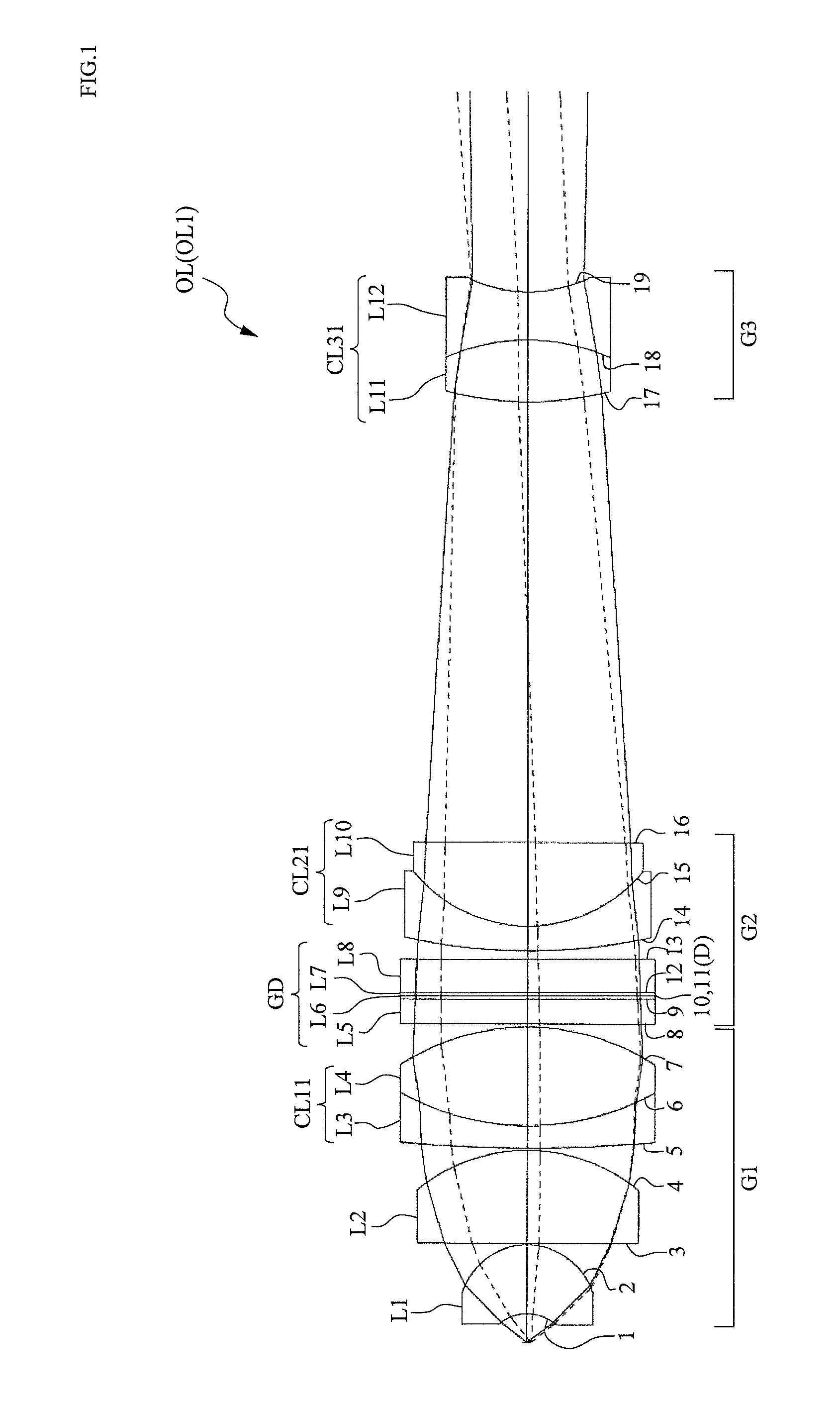
[0051]Hereinafter, preferred embodiments of the present invention will be described with reference to the drawings. First, a high-magnification microscope objective lens will be described. FIG. 1 illustrates a microscope objective lens OL according to a first embodiment comprising, in order from the object side, a first lens group G1 having a positive refractive power, a second lens group G2, and a third lens group G3 having a negative refractive power.

[0052]In the microscope objective lens OL described above, the first lens group G1 is a lens group for approximating a divergent light bundle from an object to a parallel light bundle. To this end, the first lens group G1 is configured so as to include a positive lens component (for example, a positive meniscus lens L1 illustrated in FIG. 1) having a lens surface with a negative refractive power, and at least one achromatizing lens component (a cemented lens CL11 illustrated in FIG. 1) that joins a positive lens and ...

second embodiment

[Second Embodiment]

[0072]Next, a case of a microscope objective lens having a long working distance will be described. FIG. 11 illustrates a microscope objective lens OL according to a second embodiment comprising, in order from the object side, a first lens group G1 having a positive refractive power, a second lens group G2 having a positive refractive power, and a third lens group G3 having a negative refractive power.

[0073]In the microscope objective lens OL described above, the first lens group G1 is a lens group for approximating a divergent light bundle from an object to a parallel light bundle. To this end, the first lens group G1 is configured so as to include a positive lens component (for example, a positive meniscus lens L1 illustrated in FIG. 11) having a lens surface with a negative refractive power, and at least one achromatizing lens component (a cemented lens CL11 illustrated in FIG. 11) that joins a positive lens and a negative lens. The positive lens component may ...

third embodiment

[Third Embodiment]

[0092]Finally, a low-magnification microscope objective lens will be described. FIG. 19 illustrates a microscope objective lens OL according to a third embodiment comprising, in order from the object side, a first lens group G1 having a positive refractive power, a second lens group G2, and a third lens group G3 having a negative refractive power.

[0093]In the microscope objective lens OL described above, the first lens group G1 is a lens group for approximating a divergent light bundle from an object to a parallel light bundle. To this end, the first lens group G1 is configured so as to include a positive lens component (for example, a positive meniscus lens L1 illustrated in FIG. 19) positioned nearest to the object side and having a lens surface with a negative refractive power. The positive lens component may be configured using a single lens or a cemented lens. If r denotes a curvature radius of the lens surface (for example, a first surface illustrated in FIG....


PUM


Abstract

A microscope objective lens OL includes, in order from the object side: a first lens group G1 having a positive refractive power, a second lens group G2, and a third lens group G3 having a negative refractive power, wherein the first lens group G1 includes a positive lens component L1 having a lens surface with a negative refractive power and at least one cemented lens component CL11 having a positive refractive power, the second lens group G2 includes a diffractive optical element GD that joins two diffractive element components L6 and L7 respectively made from different optical materials and which has a diffractive optical surface D on which diffractive grating grooves are formed on the bonded surface of the two diffractive element components, and at least one cemented lens component CL21, and the third lens group G3 includes at least one achromatic lens component CL31.

Description

CROSS-REFERENCE TO RELATED APPLICATIONS[0001]This application is a U.S. Continuation Application claiming priority benefit under 35 U.S.C. Section 111(a), of PCT International Application No. PCT / JP2009 / 057161, filed Apr. 8, 2009, which claims earlier priority benefit to Japanese Application No. 2008-103139, filed Apr. 11, 2008, Japanese Application No. 2008-231955, filed Sep. 10, 2008, and Japanese Application No. 2009-040281, filed Feb. 24, 2009, the entire disclosures of which are incorporated by reference as a part of this application.TECHNICAL FIELD[0002]The present invention relates to a microscope objective lens.BACKGROUND ART[0003]Conventional microscope objective lenses require large numbers of cemented lenses for favorably correcting various aberrations, in particular, chromatic aberration, and also require the use of anomalous dispersion glass materials for correcting secondary spectra. Accordingly, conventional microscope objective lenses are inevitably expensive. In rec...

Claims


Application Information

Patent Timeline
Patent Type & Authority Patents(United States)
IPC IPC(8): G02B5/18G02B21/02G02B27/00G02B27/42
CPCG02B21/02G02B27/0056G02B27/42G02B27/4211G02B27/4216
Inventor TAEKO, TOSHIAKIKO, MIYAKAWA
Owner NIKON CORP
Why Eureka
Try Eureka