Magnetic levitation screw-clamping jaw for automatic screwdrivers

a screw-clamping jaw and screw-clamping technology, which is applied in the direction of screw-clamping, wrenches, metal-working devices, etc., can solve the problems of reducing the lifecycle of automatic tools, affecting the convenience of screw-locking operation, and design cannot meet the conditions of actual applications, so as to achieve easy, fast and convenient completion, and reduce the production cost of peripheral equipment for locking screws. , the effect of high accuracy

Inactive Publication Date: 2017-04-20
HSU HSIU LIN
View PDF0 Cites 5 Cited by
  • Summary
  • Abstract
  • Description
  • Claims
  • Application Information

AI Technical Summary

Benefits of technology

[0011]The main objective of the present invention is to provide a magnetic levitation screw-clamping jaw for automatic screwdrivers used in assembly operations requiring high accuracy, and to further develop low-cost peripheral (locking) modules for automatic screwdrivers specifically used in robots. Thus, the production cost of peripheral equipment for locking screws can be reduced, and robots can easily, quickly and conveniently complete continuous and automatic screw-locking operations. This will greatly reduce production costs.

Problems solved by technology

The maximum torsion is rarely used as the maximum allowance, because using the maximum torsion will reduce the lifecycle of the automatic tools.
Hence, such designs can not meet the condition of actual applications.
Therefore, occasionally, when locking screws on airplanes, automobiles or other products, such situations as screw slippage or loose locking may occur, which may consequently leading to accidents; moreover, such chucks used to clamp screws are usually over-sized, and due to the problem of the chuck size, the convenience of screw-locking operation is often affected by the limited space.
The structural design of such existing robots and automatic screwdrivers can only be applied in traditional automatic equipment of three axes or less.
Besides, in the past, there were no robot-dedicated pneumatic screwdrivers.
Because the overall equipment uses too many modules, the manufacturing cost is greatly increased.
Secondly, in case of different sizes of screws to be locked, it is necessary to use screw fixers of matching sizes.
However, as there are many different specifications of screws, if it is necessary to change a matching screw feeder every time when changing to a different screw size, the cost will be very high.
Such productions still rely on human labor, and due to the high cost of labor, massive production is not feasible.

Method used


Image

  • Magnetic levitation screw-clamping jaw for automatic screwdrivers
  • Magnetic levitation screw-clamping jaw for automatic screwdrivers
  • Magnetic levitation screw-clamping jaw for automatic screwdrivers

Examples


Embodiment Construction

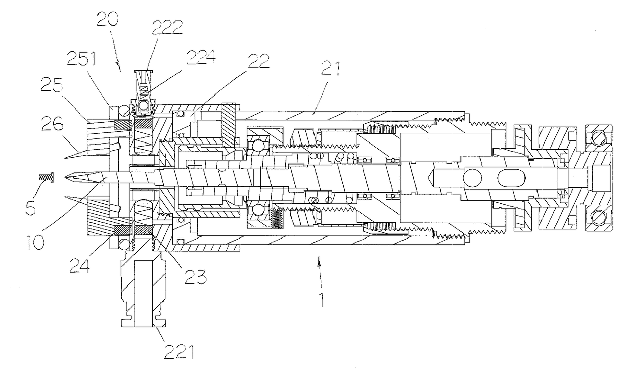
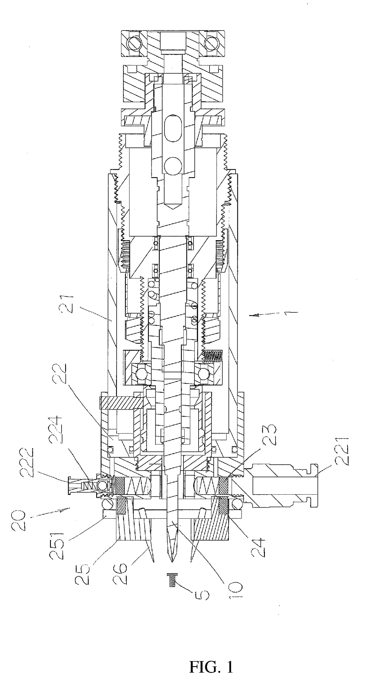
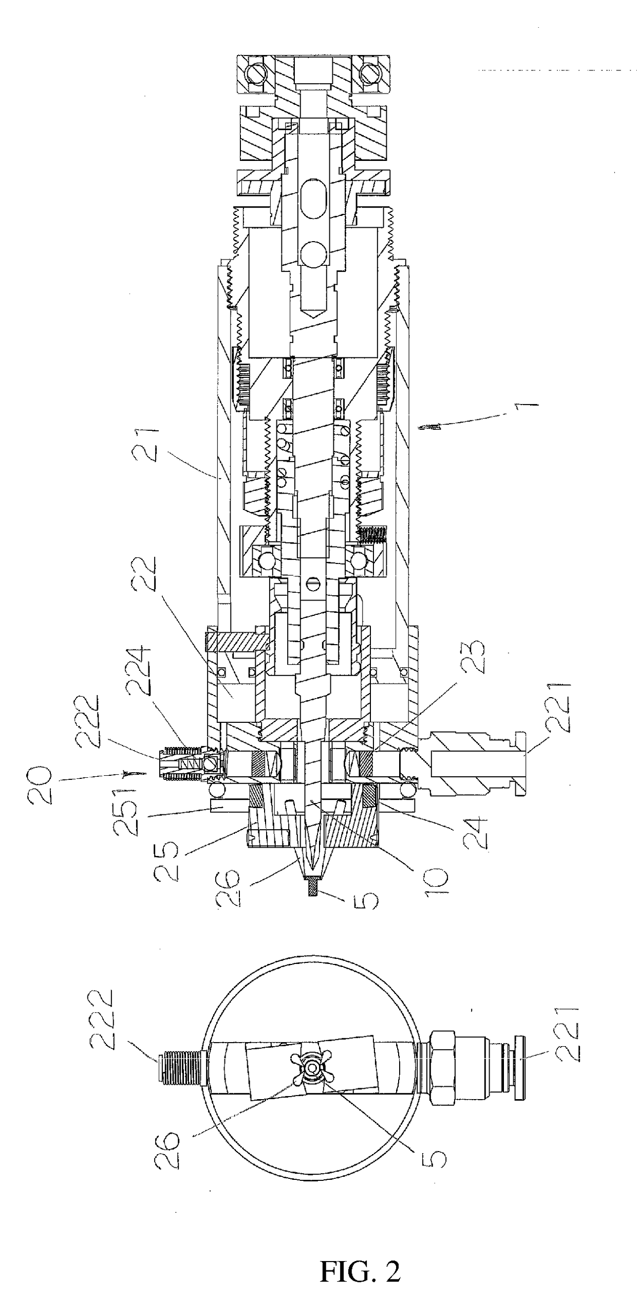
[0031]The present invention provides a magnetic levitation screw-clamping jaw for automatic screwdrivers, mainly features a configuration of a magnetic levitation clamping jaw 20 on the front end of the screwdriver bit 10 of an automatic screwdriver 1.

[0032]FIG. 1 depicts the construction of the first preferred embodiment of the magnetic levitation clamping jaw; wherein, the magnetic levitation clamping jaw 20 is configured on the front end of the screwdriver bit 10 of an automatic screwdriver 1, and the tail end of the automatic screwdriver 1 is actually combined with a robot (robotic arm) for application; as shown in the drawing, through an outer shell base 21, the magnetic levitation clamping jaw 20 is smoothly bonded with and covering the screwdriver bit 10 of the automatic screwdriver 1 for subsequent locking operations; the constitution of the magnetic levitation clamping jaw 20 at least includes: an intake control point 221 connected with external pneumatic supply to provide ...


PUM


Abstract

A magnetic levitation screw-clamping jaw for automatic screwdrivers. The main feature is a configuration of a magnetic levitation clamping jaw on the front end of the screwdriver bit of an automatic screwdriver. The structure and working principle of the invention include: (1) through pneumatic control, clamp the screw at air intake, and through electromagnetic control, release the screw at air exhaust, meanwhile complete the locking action straightforward with the automatic screwdriver; and with electric power input, the electromagnet can absorb the screw; (2) through the relative displacement with the automatic screwdriver, push the magnet, and as like poles repel, the repulsion force will push the displacement to clamp the screw to immediately conduct the locking action; (3) through the relative displacement with the automatic screwdriver, push the switch to control the magnet excitation of the magnetic chuck to absorb and clamp the screw for the screw-locking action.

Description

BACKGROUND OF INVENTION[0001]1. Field of the Invention[0002]The present invention relates generally to screw-locking technology used in robots (or robotic arms), and more particularly to a magnetic levitation screw-clamping jaw for automatic screwdrivers which is more convenient, more accurate and more effective.[0003]2. Description of Related Art[0004]Nowadays, automatic screwdrivers are commonly used in robots or robotic arms for screw-locking operations. In an automatic screw-locking operation, the screwdriver bit on the front end of the automatic screwdriver is aligned to the screw clamped from the screw aligner (or screw storage trough) on the robot or robotic arm and then the screw is locked and fixed.[0005]To cater to various types of operation, manufacturers have constantly developed various products to meet specific needs; for example, prior-art domestic Patent Publication No. M343563 “screw supplying device” disclosed a screw supplying device to combine with an automatic s...

Claims


Application Information

Patent Timeline
Patent Type & Authority Applications(United States)
IPC IPC(8): B23P19/06
CPCB23P19/06B25B23/10B25B23/12
Inventor HSU, HSIU-LIN
Owner HSU HSIU LIN
Why Eureka
Try Eureka