Illumination apparatus

a technology of a heat dissipation apparatus and a fin is applied in the direction of lighting and heating apparatus, lighting support devices, and semiconductor/solid-state device details. it can solve the problems of low heat dissipation efficiency, achieve greater width of heat dissipation fins, prevent air stagnation, and enhance heat dissipation efficiency.

Inactive Publication Date: 2011-05-05
YOUNG GREEN ENERGY
View PDF5 Cites 14 Cited by
  • Summary
  • Abstract
  • Description
  • Claims
  • Application Information

AI Technical Summary

Benefits of technology

[0009]Accordingly, the invention is directed to an illumination apparatus having a good heat dissipation efficiency.
[0012]In view of the foregoing, the embodiment of the invention has at least one of the following advantages. The groove formed by the heat dissipation fins provides a space for the air to flow, thereby preventing air stagnancy at a central area of the heat dissipation fins and hence enhancing the heat dissipation efficiency. Additionally, the width of each heat dissipation fin is greater than the width of the heat dissipation base. Therefore, each of heat dissipation fins extends outwardly from two sides of the heat dissipation base and is positioned opposite to the bottom wall, and the heat dissipation fins extend over and beyond the air inlets, thus facilitating the airflow entering via the air inlets sufficiently contacting each heat dissipation fin so as to further enhance the heat dissipation efficiency.

Problems solved by technology

However, the airflow stagnancy may easily occur at a central area A1 of the heat dissipation fins 54 and therefore the heat of the heat dissipation fins 54 may not be effectively taken away, such that the temperature of the central area A1 may not be lowered thus resulting in a low heat dissipation efficiency.

Method used


Image

  • Illumination apparatus
  • Illumination apparatus
  • Illumination apparatus

Examples


Embodiment Construction

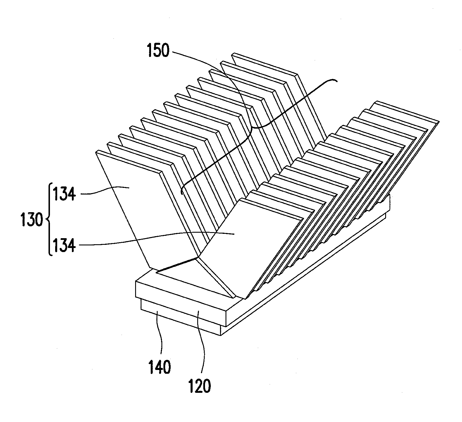
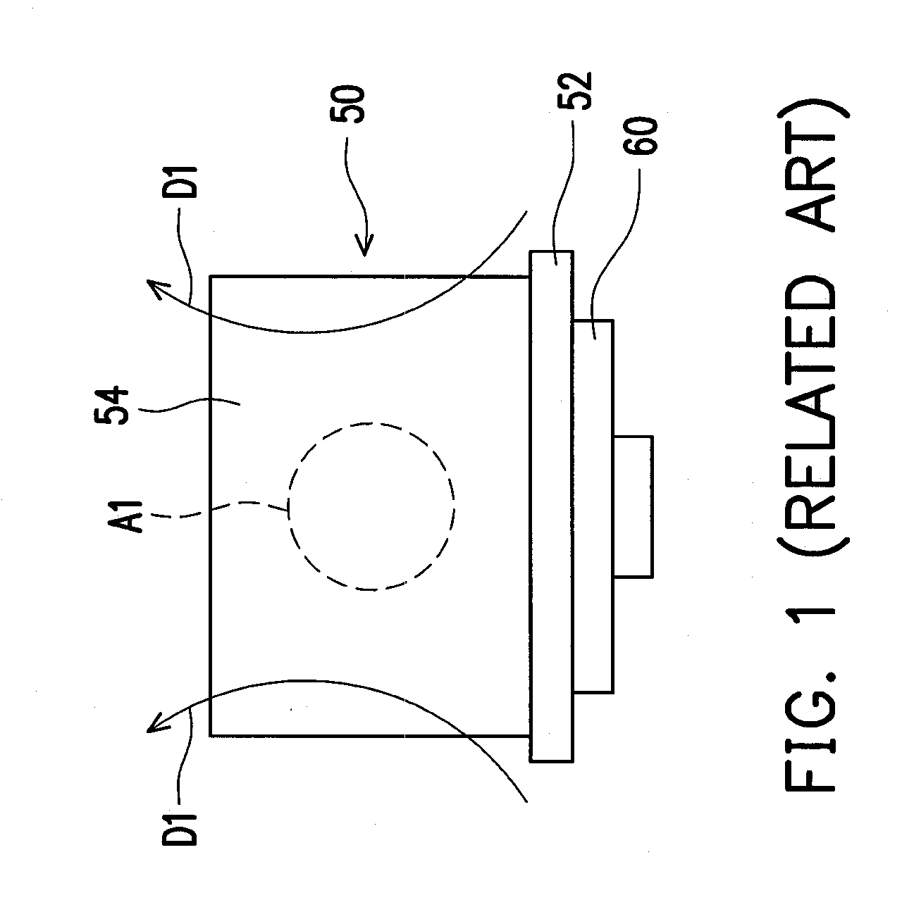
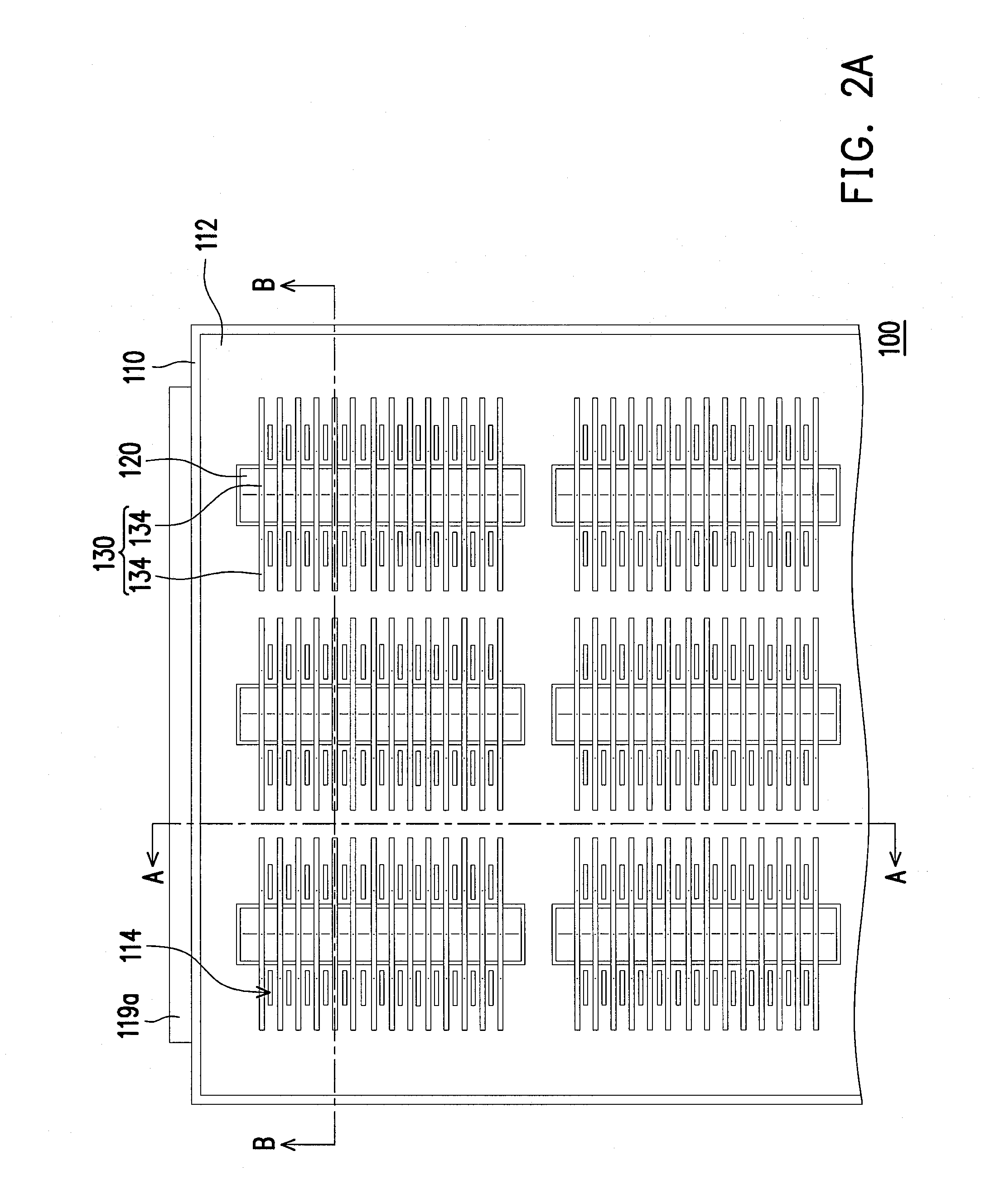
[0023]In the following detailed description of the preferred embodiments, reference is made to the accompanying drawings which form a part hereof, and in which are shown by way of illustration specific embodiments in which the invention may be practiced. In this regard, directional terminology, such as “top,”“bottom,”“front,”“back,” etc., is used with reference to the orientation of the Figure(s) being described. The components of the present invention can be positioned in a number of different orientations. As such, the directional terminology is used for purposes of illustration and is in no way limiting. On the other hand, the drawings are only schematic and the sizes of components may be exaggerated for clarity. It is to be understood that other embodiments may be utilized and structural changes may be made without departing from the scope of the present invention. Also, it is to be understood that the phraseology and terminology used herein are for the purpose of description an...


PUM


Abstract

An illumination apparatus includes an outer housing, a heat dissipation base, a plurality of heat dissipation fins, and a light source. The outer housing has a bottom wall with an air inlet and an opening. The heat dissipation base is connected to the bottom wall. The heat dissipation fins are connected to the heat dissipation base and the heat dissipation fins are substantially parallel to each other. Each of the heat dissipation fins has a concave and the concaves of the heat dissipation fins cooperatively form a groove. The orthographic projection area overlaps the air inlet. The light source is connected to the heat dissipation base and exposed through the opening. The illumination apparatus has a good heat dissipation efficiency.

Description

CROSS-REFERENCE TO RELATED APPLICATION[0001]This application claims the priority benefit of China application serial no. 200910207689.4, filed on Oct. 29, 2009. The entirety of the above-mentioned patent application is hereby incorporated by reference herein and made a part of this specification.BACKGROUND OF THE INVENTION[0002]1. Field of the Invention[0003]The invention relates to an illumination apparatus.[0004]2. Description of Related Art[0005]With the continuous improvements on luminance and illumination efficiency of light emitting diodes (LEDs), illumination apparatus have started using LED as a light source in recent years. However, during operation, the LED generates heat and the heat may be removed to maintain the LED to operate within a normal operating temperature range.[0006]The LED has been used as a light source for street lights. Heat generated by this type of street light may be dissipated by a loop heat pipe, a fan in combination with a fin-type heat sink, a heat ...

Claims


Application Information

Patent Timeline
Patent Type & Authority Applications(United States)
IPC IPC(8): F21S4/00F21V29/00
CPCF21V29/004F21W2131/103F21Y2101/02H01L23/3672F21V29/71H01L2924/0002F21V29/745F21V29/76H01L2924/00F21Y2115/10F21V29/83
Inventor WANG, CHENGCHOU, PO-KUEI
Owner YOUNG GREEN ENERGY
Why Eureka
Try Eureka