
Mobile Aircraft Inspection System

a mobile aircraft and inspection system technology, applied in the direction of material analysis using wave/particle radiation, instruments, optics, etc., can solve the problems of inability to effectively discriminate between typical metals and special nuclear materials, difficult inspection of a complete aircraft, and inability to effectively detect typical metals

Active Publication Date: 2011-05-05
RAPISCAN SYST INC (US)
View PDF36 Cites 45 Cited by
  • Summary
  • Abstract
  • Description
  • Claims
  • Application Information

AI Technical Summary

Benefits of technology

[0011]The inspection system of the present invention is not only rapid and non-intrusive, but also safe for all personnel in the immediate area of the aircraft, including the system operator, ground personnel and personnel on the aircraft. The system of the present invention is, in one embodiment, designed to be mobile, such that it can be delivered to any airfield and operate independently from other equipment and machines on the airfield.

Problems solved by technology

Inspection of a complete aircraft however, can be challenging with a transmission-based geometry wherein typically, the source is located on one side of the aircraft and detectors are located on the other side of the aircraft.
This geometry has many challenges, and in particular, when scanning around the landing gear and engines as there is difficulty placing detectors and thus, in producing radiographic images.
However, backscatter technology may not be suitable when all areas of the aircraft have to be penetrated with a high detection probability, such as is the case with nuclear materials detection.
In addition, backscatter technology cannot effectively discriminate between typical metals and special nuclear materials.
Conventional X-ray backscatter and transmission systems, however, do not have adequate scanning robustness, ability to work in various orientations, scanning range, or field of view for aircraft inspection applications.

Method used


Image

  • Mobile Aircraft Inspection System
  • Mobile Aircraft Inspection System
  • Mobile Aircraft Inspection System

Examples


second embodiment

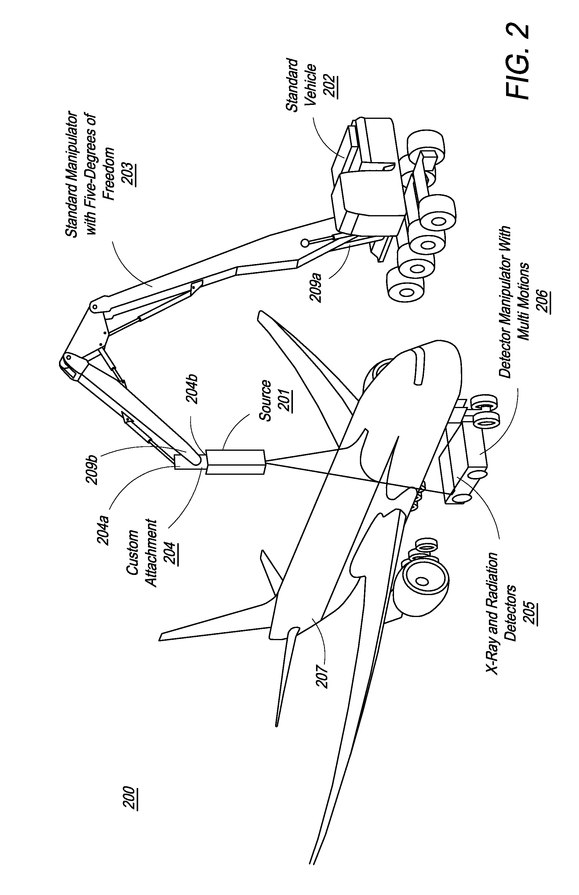
[0056]Further, the present invention is described with reference to X-ray transmission imaging. For the purpose of aircraft inspection based on transmission technology, the X-ray energy is optimized in the range of 200 kV to 1 MV, when detection of nuclear materials is not required, depending on the size of the aircraft. The optimized energy range increases from 1 MV to 9 MV when nuclear material detection is required. The source could generate a single-energy distribution or multiple-energy distributions.

third embodiment

[0057]Still further, in a third embodiment, the present invention advantageously employs both backscatter and transmission imaging. Thus, any imaging system that has the potential for displaying object detail may be employed in the system and methods of the present invention.

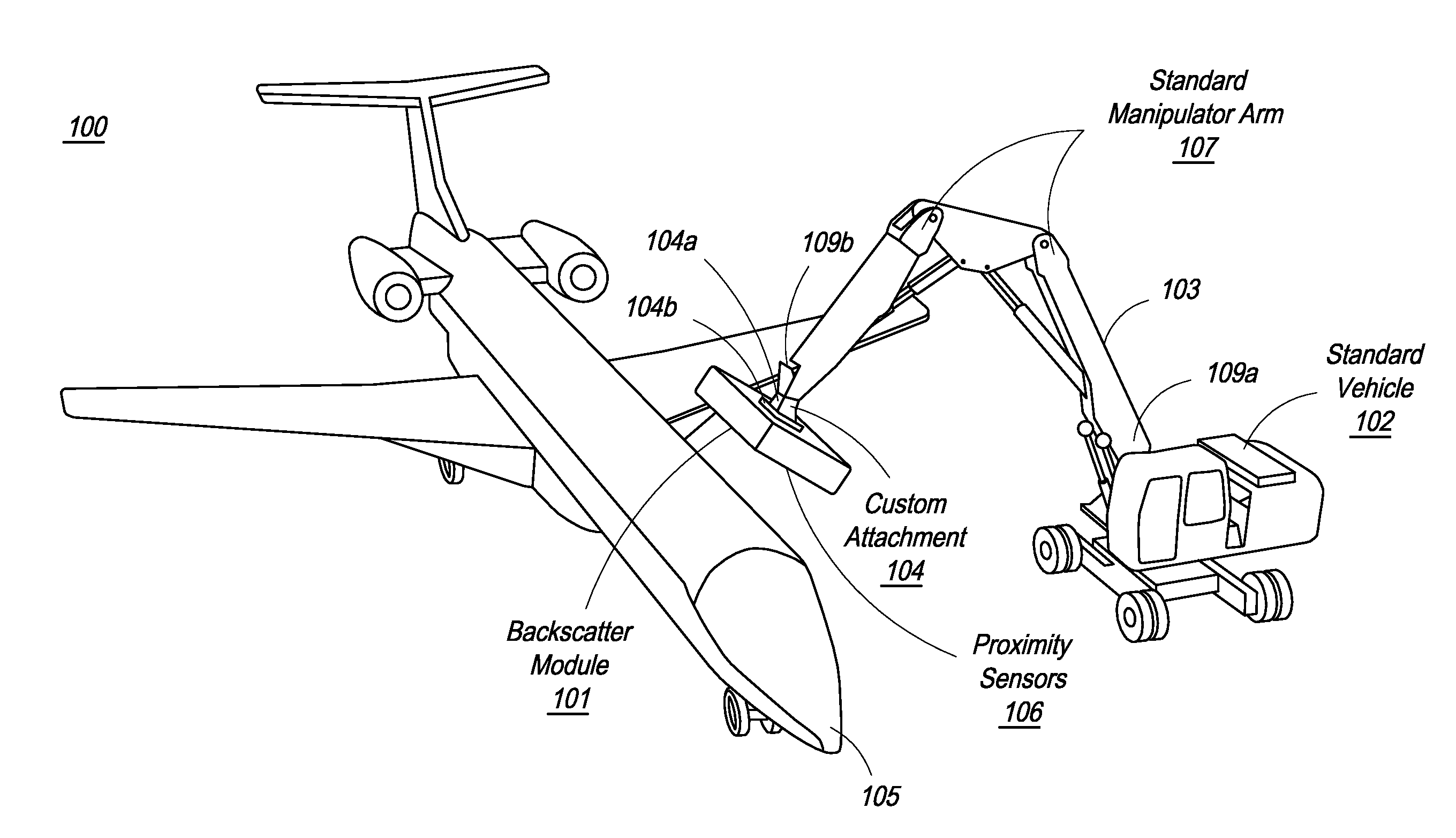
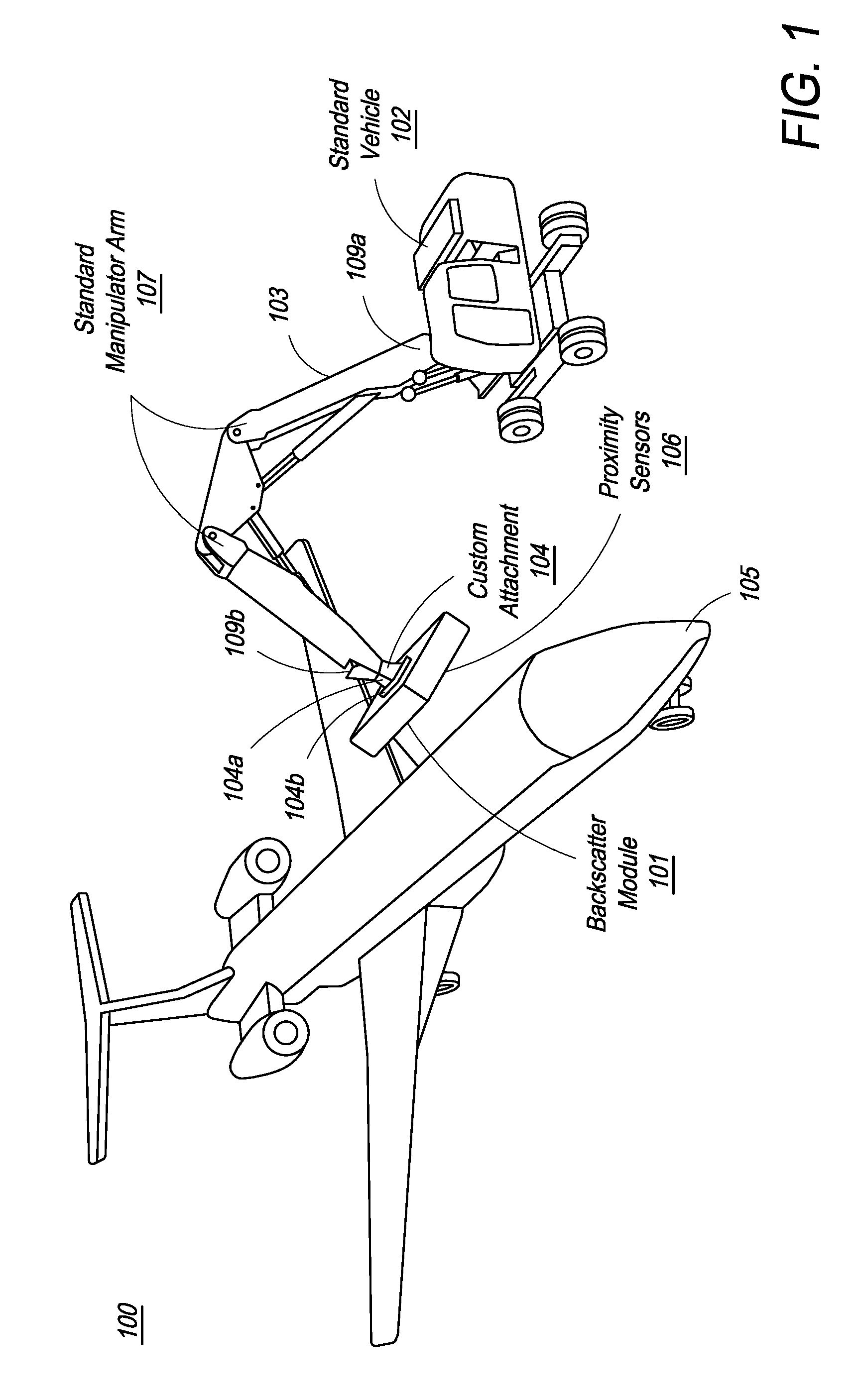
[0058]FIG. 1 illustrates the overall system design of one embodiment of the present invention. Referring to FIG. 1, aircraft inspection system 100, in one embodiment, comprises inspection head 101, vehicle or transport cart 102, and manipulator arm 103. In one embodiment, inspection head 101 comprises a backscatter inspection module, further comprising an X-ray source, a beam scanning mechanism and X-ray detectors. The backscatter inspection module is described in greater detail below with respect to FIG. 4. In one embodiment, vehicle or transport cart 102 is any standard vehicle suitable for movement about an aircraft 105.

[0059]In one embodiment, vehicle 102 is movably connected to first, proximal end 109a of m...


PUM


Abstract

A system for scanning aircraft for concealed threats is provided. The system comprises a vehicle and a manipulator arm attached with a scanning head that can be maneuvered in multiple directions to completely scan an aircraft from the outside. The system uses transmission based X-ray detection, backscatter based X-ray detection or a combination thereof, in various embodiments. The system also includes gamma-ray and neutron detectors, for detection of nuclear and radioactive materials.

Description

CROSS-REFERENCE TO RELATED APPLICATIONS[0001]The present invention relies on U.S. Provisional Patent Application No. 61 / 256,104, entitled “Mobile Aircraft Inspection System” and filed on Oct. 29, 2009, for priority and is herein incorporated by reference in its entirety.FIELD OF THE INVENTION[0002]The present invention generally relates to the field of radiant energy imaging systems for detecting concealed objects, and more specifically to an X-ray inspection system for inspecting aircraft for threat items and other contraband.BACKGROUND OF THE INVENTION[0003]In current times, with increasing threats of violence, the inspection of vehicles in addition to luggage and cargo at transit points has become almost universally mandatory. In addition to passenger and cargo vehicles, contraband such as explosives, weapons, narcotics, dangerous chemicals, and nuclear and radioactive materials can also be concealed in various parts of general aircraft for illegal transportation. Detection of su...

Claims


Application Information

Patent Timeline
IPC IPC(8): G01N23/04
CPCG01V5/0008G01V5/0091G01V5/0025G01V5/0016G01N23/04G01N2223/1006G01N2223/1013G01N2223/1016G01N2223/106G01N2223/631G01N2223/3303G01V5/20G01V5/222G01N23/083G01N23/203G03B42/028H05G1/02G01N23/05G01V5/232G01V5/22
Inventor BENDAHAN, JOSEPH
Owner RAPISCAN SYST INC (US)
Learn More