
Bottle With Integral Dip Tube

a technology of dip tubes and spray connectors, which is applied in the direction of liquid transfer devices, single-unit apparatuses, packaging, etc., can solve the problems of additional manufacturing costs, unfavorable use, and inability to meet the requirements of use,

Active Publication Date: 2011-05-12
THE CLOROX CO
View PDF25 Cites 28 Cited by
  • Summary
  • Abstract
  • Description
  • Claims
  • Application Information

AI Technical Summary

Benefits of technology

[0016]The use of the bottle of the present invention, from a consumer perspective, would not differ from the use of any conventional trigger or pump bottle known in the art. The user would simply activate the fluid dispensing mechanism to dispense fluid from the bottle.
[0017]In one embodiment, the bottle may include a snap-fit fluid dispensing mechanism, such as a pump or a trigger sprayer, for dispensing fluid from the container. By using a snap-fit mechanism instead of a screw-type mechanism, alignment and sealing attachment of the mechanism to the container may be achieved in a single motion. This is in contrast to the prior art screw-type mechanisms, where attachment of the mechanism to the container includes at least a first motion of alignment, which includes maintaining this alignment throughout a second motion of rotation to tighten the mechanism on the container to form a seal.

Problems solved by technology

Sprayer connectors with conventional dip tubes present problems.
Warped dip tubes are currently a major problem in the pump / bottle assemblies with a resultant undesired amount of scrap.
The requirements of an upstanding projection and offset supply tube may result in additional manufacturing cost.
Without such an upstanding projection, the torque of tightening the screw cap onto the bottle may misalign the integral dip tube from the offset supply tube.
Thus, the problems associated with standard dip tubes, as discussed above, may apply to the typical bayonet sprayer connectors currently in use.
For bayonet connectors, the rotation of the sprayer connector relative to the container neck after alignment of the supply tube with the integral dip tube could create problems in maintaining that alignment and connection with the integral dip tube.

Method used


Image

  • Bottle With Integral Dip Tube
  • Bottle With Integral Dip Tube
  • Bottle With Integral Dip Tube

Examples


Embodiment Construction

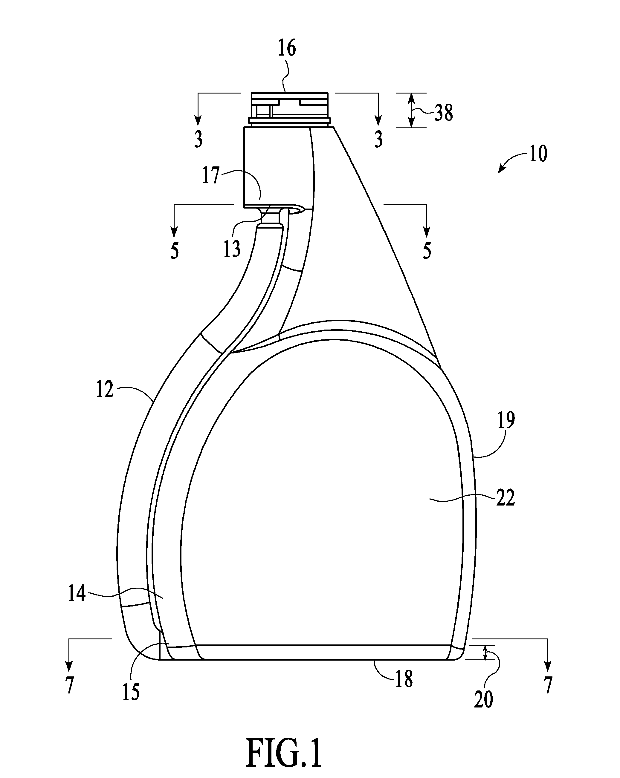
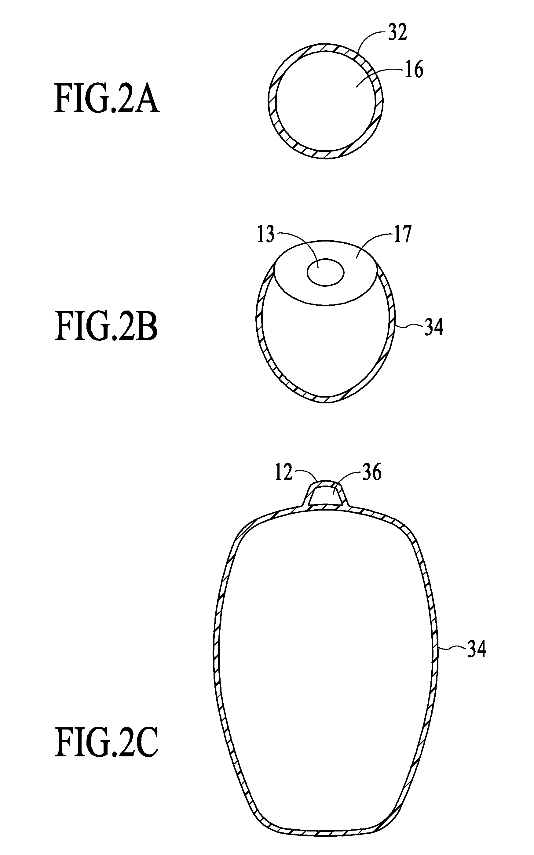
[0039]Reference will now be made to the drawings wherein like numerals refer to like parts throughout. For ease of description, the components of this invention are described in the normal (upright) operating position, and terms such as upper, lower, horizontal, etc., are used with reference to this position. It will be understood, however, that the components embodying this invention may be manufactured, stored, transported, used, and sold in an orientation other than the position described.

[0040]Figures illustrating the components of this invention show some conventional mechanical elements that are known and that will be recognized by one skilled in the art. The detailed descriptions of such elements are not necessary to an understanding of the invention, and accordingly, are herein presented only to the degree necessary to facilitate an understanding of the novel features of the present invention.

[0041]All publications, patents and patent applications cited herein, whether supra...


PUM


Abstract

Described is a fluid dispensing container having a bottle and fluid withdrawing assembly for liquids, such as liquid cleaners and the like. The bottle has an integral dip tube formed therein connecting at a landing below the top of the bottle neck, fluidly connecting the inside of the bottle with the top opening of the bottle. A fluid dispensing mechanism, such as a pump or trigger-sprayer, is attached to the top of the bottle to take fluid up through the integral dip tube and dispense the fluid accordingly. The fluid dispensing mechanism may be aligned to allow a direct connection between integral dip tube and the fluid dispensing mechanism at a landing below the bottle opening. The fluid dispensing mechanism may be attached to the bottle with a snap-fit connection.

Description

BACKGROUND OF THE INVENTION[0001]1. Field of the Invention[0002]This invention relates generally to containers and fluid withdrawing assemblies for liquids, such as liquid cleaners and the like. More particularly, the present invention relates generally to bottles having an integral supply tube formed therein. In particular, the present invention relates to the connection of a trigger sprayer to a bottle with a snap-on fitment and connection to an integral supply tube or dip tube.[0003]2. Description of the Related Art[0004]Trigger sprayers are those types of sprayers that can be held in a single hand of the user and operated by the fingers of the user's hand to pump fluid from a container connected to the trigger sprayer. A prior art trigger sprayer typically includes a sprayer housing that contains a pump chamber and piston, and a sprayer fluid supply passageway that fluidly communicates a fluid inlet opening (sometimes also referred to as a “connector aperture”) with the pump cha...

Claims


Application Information

Patent Timeline
Patent Type & Authority Applications(United States)
IPC IPC(8): B05B11/00B67D7/58
CPCB05B11/001B05B11/0037B05B11/3011B05B11/3057B05B15/005B05B11/0089B05B11/3045B05B15/30B05B11/1011B05B11/1045
Inventor DENNIS, STEPHEN R.
Owner THE CLOROX CO
Features
  • Generate Ideas
  • Intellectual Property
  • Life Sciences
  • Materials
  • Tech Scout
  • Unparalleled Data Quality
  • Higher Quality Content
  • 60% Fewer Hallucinations
Learn More