Plate wave element and electronic equipment using same

a technology of plate wave element and electronic equipment, applied in piezoelectric/electrostrictive/magnetostrictive devices, piezoelectric/electrostriction/magnetostriction machines, electrical equipment, etc., can solve problems such as reducing the strength of elements

Active Publication Date: 2011-05-12
SKYWORKS PANASONIC FILTER SOLUTIONS JAPAN
View PDF8 Cites 117 Cited by
  • Summary
  • Abstract
  • Description
  • Claims
  • Application Information

AI Technical Summary

Problems solved by technology

The small thickness reduces the strength of the element, accordingly producing a crack due to a stress applied to piezoelectric body 103.

Method used


Image

  • Plate wave element and electronic equipment using same
  • Plate wave element and electronic equipment using same
  • Plate wave element and electronic equipment using same

Examples


exemplary embodiment 1

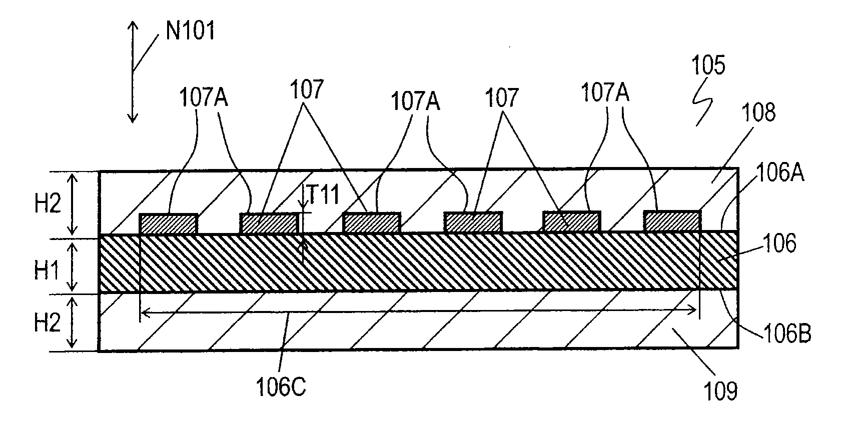
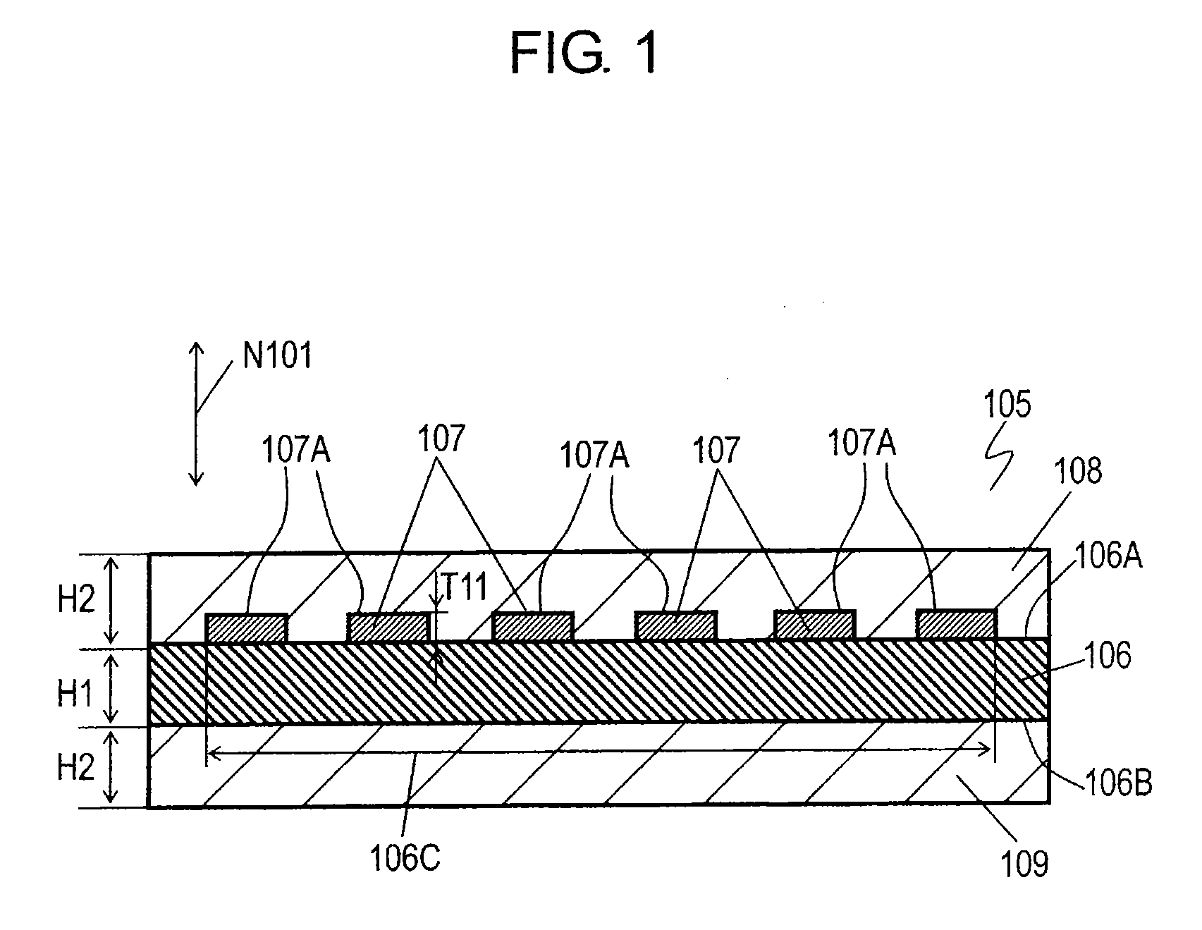
[0024]FIG. 1 is a schematic sectional view of plate wave element 105 in accordance with a first exemplary embodiment of the present invention. Plate wave element 105 includes piezoelectric body 106, comb-shaped electrode 107 disposed on upper surface 106A of piezoelectric body 106, medium layer 108 disposed on upper surface 106A of piezoelectric body 106 and upper surface 107A of comb-shaped electrode 107 so as to cover comb-shaped electrode 107, and medium layer 109 disposed on lower surface 106B of piezoelectric body 106. Comb-shaped electrode 107 is disposed in exciting region 106C of upper surface 106A of piezoelectric body 106. Medium layer 109 is positioned directly below exciting region 106C. Comb-shaped electrode 107 excites exciting region 106C of piezoelectric body 106 to make piezoelectric body 106 generate and propagate a plate wave. A main component of the propagated plate wave is a Lamb wave in plate wave element 105. Piezoelectric body 106, comb-shaped electrode 107, ...

exemplary embodiment 2

[0050]FIG. 7 is a schematic sectional view of plate wave element 205 in accordance with Exemplary Embodiment 2. Plate wave element 205 includes piezoelectric body 206, comb-shaped electrode 207 disposed on upper surface 206A of piezoelectric body 206, medium layer 208 disposed on upper surface 206A of piezoelectric body 206 and upper surface 207A of comb-shaped electrode 207 so as to cover comb-shaped electrode 207, and medium layer 209 disposed on lower surface 206B of piezoelectric body 206. Comb-shaped electrode 207 is disposed in exciting region 206C of upper surface 206A of piezoelectric body 206. Medium layer 209 is positioned directly below exciting region 206C. Piezoelectric body 206, comb-shaped electrode 207, and medium layers 208 and 209 are stacked in normal direction N201 perpendicular to upper surface 206A and lower surface 206B of piezoelectric body 206. Piezoelectric body 206 has thickness H21 in normal direction N201. Each of medium layers 208 and 209 has thickness ...


PUM


Abstract

A plate wave element includes a piezoelectric body, a comb-shaped electrode disposed on an upper surface of the piezoelectric body, and a medium layer disposed on the upper surface of the piezoelectric body so as to cover the comb-shaped electrode. The comb-shaped electrode excites a Lamb wave as a main wave. The medium layer has a frequency temperature characteristic opposite to that of the piezoelectric body. The plate wave element has a preferable frequency temperature characteristic.

Description

TECHNICAL FIELD[0001]The present invention relates to a plate wave element through which plate waves propagates, and an electronic device using the plate wave element.BACKGROUND ART[0002]FIG. 17 is a schematic sectional view of conventional plate wave element 101 disclosed in Patent Literature 1. Plate wave element 101 has base substrate 102 and piezoelectric body 103 that is formed on base substrate 102. Piezoelectric body 103 is formed on upper surface 102A of base substrate 102, and a part of piezoelectric body 103 is removed from upper surface 102A of base substrate 102. In the removed part, lower surface 103A of piezoelectric body 103 faces upper surface 102A of base substrate 102 across space 111 between lower surface 103A and upper surface 102A. Comb-shaped electrode 104 is formed on upper surface 103B of piezoelectric body 103 opposite to lower surface 103A. Comb-shaped electrode 104 excites a plate wave, and plate wave element 101 can form a resonator and a filter.[0003]Con...

Claims


Application Information

Patent Timeline
Patent Type & Authority Applications(United States)
IPC IPC(8): H01L41/053
CPCH03H9/02559H03H9/02834H03H9/02574H03H9/02228
Inventor GOTO, REINAKANISHI, HIDEKAZUNAKAMURA, HIROYUKI
Owner SKYWORKS PANASONIC FILTER SOLUTIONS JAPAN
Why Eureka
Try Eureka