Acoustic boundary wave device

a boundary wave and acoustic wave technology, applied in the direction of electrical transducers, generators/motors, devices material selection, etc., can solve the problems of increasing the cost of surface acoustic wave devices, reducing the second medium layer, and reducing the size of acoustic wave devices. , to achieve the effect of superior frequency characteristics

Active Publication Date: 2006-06-29
MURATA MFG CO LTD
View PDF10 Cites 61 Cited by
  • Summary
  • Abstract
  • Description
  • Claims
  • Application Information

AI Technical Summary

Benefits of technology

[0016] In order to overcome the problems described above, preferred embodiments of the present invention provide a boundary acoustic wave device that prevents a plurality of spurious responses in the region higher than the resonant frequency or the pass band and exhibits superior frequency characteristics.

Problems solved by technology

The use of the package having the recess or the hole inevitably increases the cost of the surface acoustic wave device.
Thus, the package having the recess or hole is unnecessary, and the acoustic wave device can be thus downsized accordingly.
However, their and the second medium layer is infinite.
However, their thicknesses in practice are finite.
Also, the boundary acoustic wave devices of the above-mentioned documents undesirably produce spurious responses in their resonance characteristics or filter characteristics.
Hence, a boundary acoustic wave resonator including such a boundary acoustic wave device is liable to produce a plurality of considerable spurious responses in the frequency region higher than the resonant frequency.
Also, a filter made of a plurality of known boundary acoustic wave resonators, for example, a ladder-shaped filter, produces a plurality of spurious responses in the frequency region higher than the pass band, thus degrading the out-of-band attenuation disadvantageously.

Method used


Image

  • Acoustic boundary wave device
  • Acoustic boundary wave device
  • Acoustic boundary wave device

Examples


Embodiment Construction

[0110] The present invention will be further described in detail by way of specific preferred embodiments with reference to the drawings.

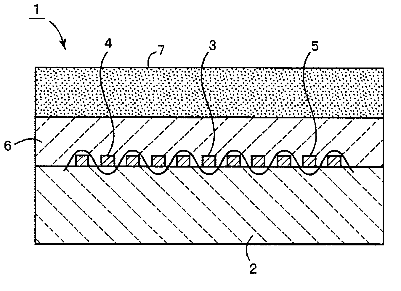
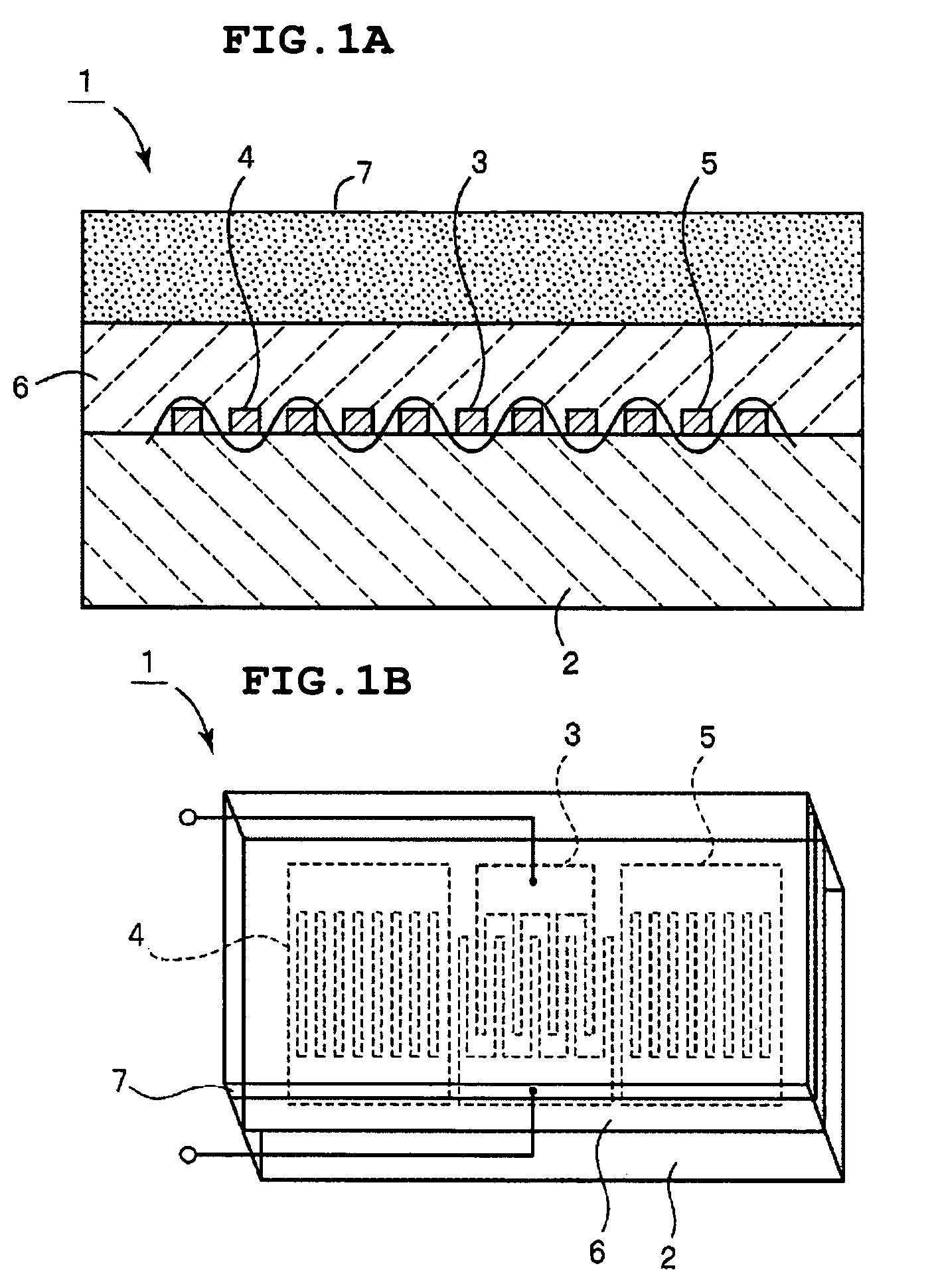
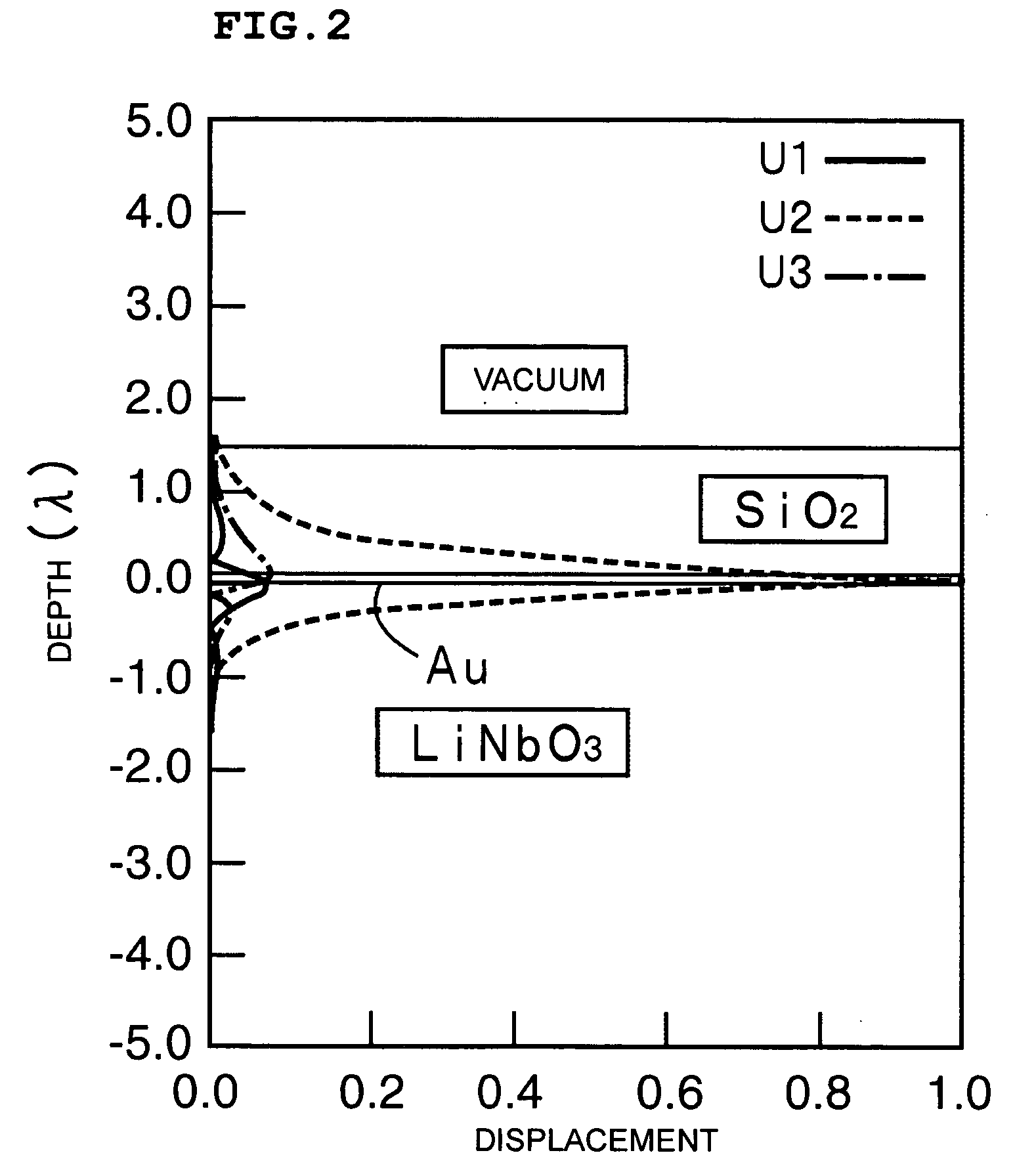
[0111] The present inventors conducted a numerical analysis to find the cause of the above-described spurious responses. This numerical analysis was based on the method disclosed in the literature “A Method For Estimating Optimal Cuts and Propagation Directions For Excitation and Propagation Directions For Excitation of Piezoelectric Surface Waves” (J. J. Campvell and W. R. Jones, IEEE Trans. Sonics and Ultrasonics, Vol. SU-15 (1968), pp. 209-217). In this analysis, the displacements and the vertical stress at the interfaces between SiO2 and Au and between the Au and LiNbO3 were continuous, and the potential was 0 by the short-circuited interfaces. The SiO2 had a predetermined thickness and the thickness of the 15° Y—X propagating LiNbO3 was unlimited. The displacement distribution of the boundary waves and spurious modes were thus examined.

[0112...


PUM

PropertyMeasurementUnit
temperatureaaaaaaaaaa
frequencyaaaaaaaaaa
densityaaaaaaaaaa

Abstract

A boundary acoustic wave device using SH boundary acoustic waves includes a first medium layer, a second medium layer stacked on the first medium layer, and an electrode including an interdigital electrode and reflectors. A sound absorbing layer is provided on the surface of the first medium layer and/or the second medium layer opposite the interface therebetween.

Description

BACKGROUND OF THE INVENTION [0001] 1. Field of the Invention [0002] The present invention relates to boundary acoustic wave devices using SH (shear horizontal) boundary acoustic waves, and more specifically, the present invention relates to a boundary acoustic wave device having an electrode in the interface between a piezoelectric material and a dielectric material. [0003] 2. Description of the Related Art [0004] Various types of surface acoustic wave devices have been used in RF and IF filters for cellular phones, VCO resonators, and VIF filters for televisions. Surface acoustic wave devices use surface acoustic waves, such as Rayleigh waves or first leaky waves propagating along the surface of a medium. [0005] Since surface acoustic waves propagate along the surface of a medium, they are sensitive to the changes of the medium state. Accordingly, in order to protect the surface acoustic wave propagating surface of the medium, the surface acoustic wave element is enclosed in a pack...

Claims


Application Information

Patent Timeline
Patent Type & Authority Applications(United States)
IPC IPC(8): H03H9/25H01L41/09H01L41/18H01L41/22H01L41/23H01L41/29H01L41/338H03H3/08H03H9/02H03H9/10H03H9/145
CPCH03H3/08H03H9/0222H03H9/02929H03H9/059H03H9/1078Y10T29/49798Y10T29/49005Y10T29/49007Y10T29/42Y10T29/4908H04R31/00H03H9/145
Inventor KANDO, HAJIME
Owner MURATA MFG CO LTD
Why Eureka
Try Eureka