Touch display panel and display apparatus

a display panel and touch technology, applied in the field of touch display panel and display apparatus, can solve the problems of low screen printing accuracy, low manufacturing precision, and difficulty in reducing line width and transmitting line pitch, and achieve low transmitting line resistance and high manufacturing precision

Inactive Publication Date: 2011-04-07
AU OPTRONICS CORP
View PDF7 Cites 61 Cited by
  • Summary
  • Abstract
  • Description
  • Claims
  • Application Information

AI Technical Summary

Benefits of technology

[0009]The disclosure is directed to a touch display panel having

Problems solved by technology

Therefore, the cost for manufacturing the panel is not increased.
In addition, the precision of the screen printing method is not desirable, and thus the line width and the pitch of the transmitting lines 122 are difficultly reduced.
In other words, a width W of the non-display area A2 of the touch panel 100 is further

Method used


Image

  • Touch display panel and display apparatus
  • Touch display panel and display apparatus
  • Touch display panel and display apparatus

Examples


Embodiment Construction

Touch Display Panel

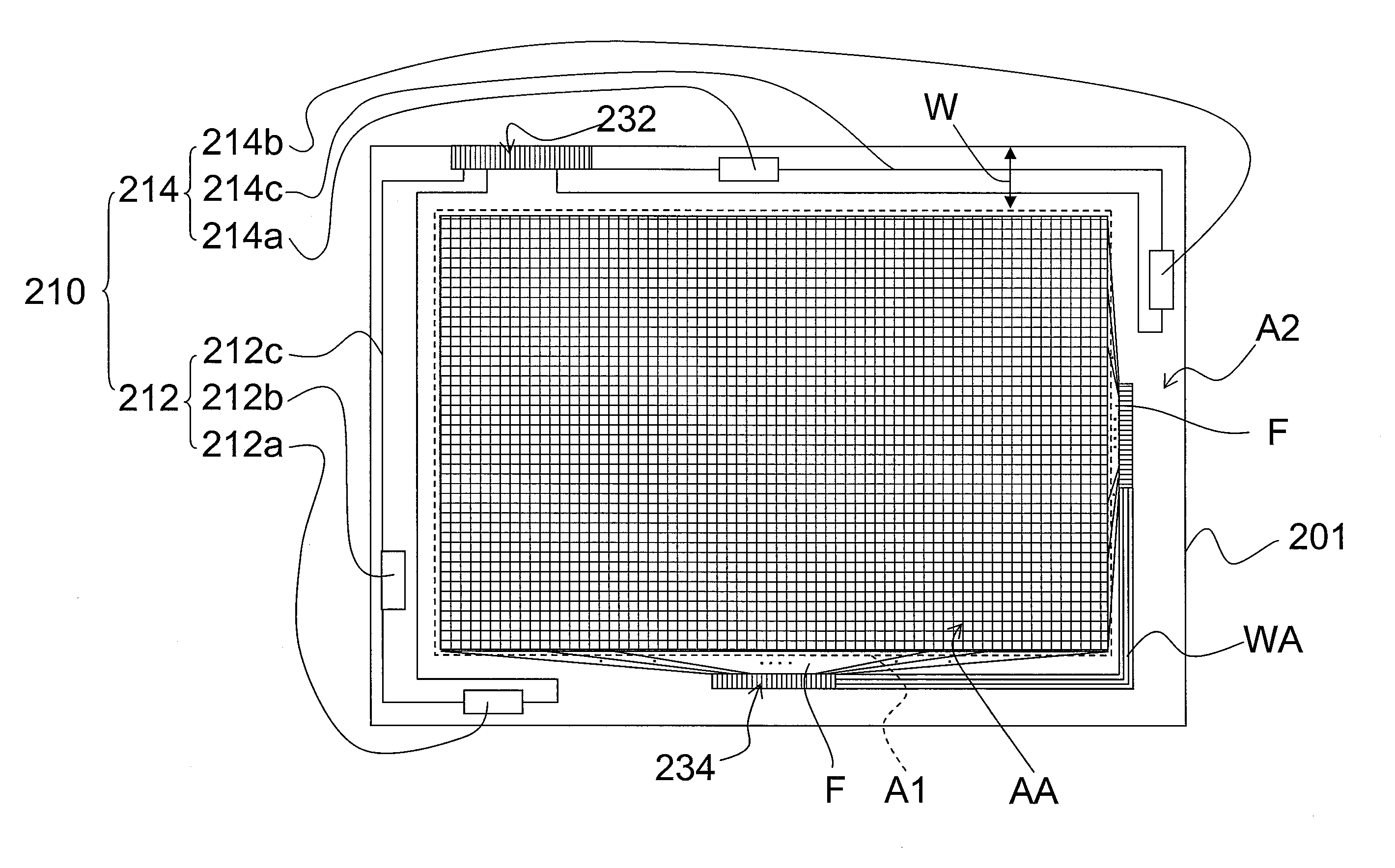
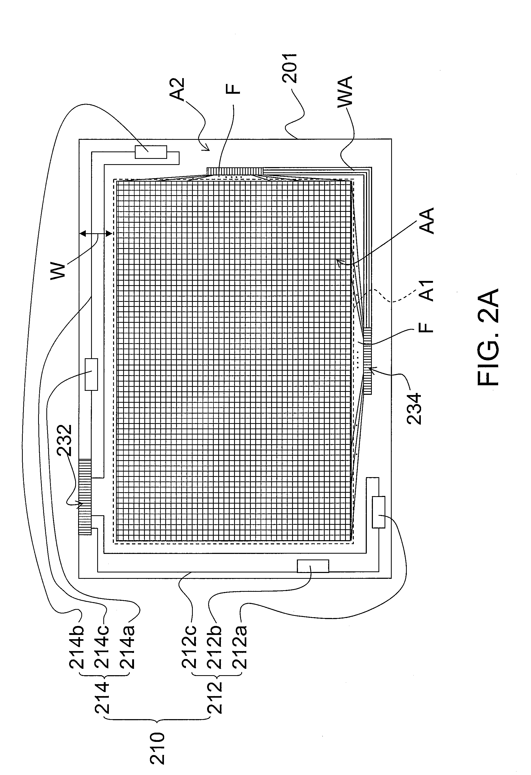
[0037]FIG. 2A is a schematic top view of a first substrate and the elements disposed thereon in a touch display panel according to an embodiment of the disclosure. FIG. 3A is a schematic side view showing a touch display panel according to an embodiment of the disclosure.

[0038]Referring to FIG. 2A, a touch sensing device 210 is disposed on a first substrate 201. The first substrate 201 has a display area A1 and a non-display area A2 located outside the display area A1. The touch sensing device 210 may be directly disposed on the first substrate 201, and located within the non-display area A2, wherein the touch sensing device 210 is consisted of two or more groups of receiving elements 212 and 214.

[0039]Specifically, the receiving elements 212 is consisted of the piezoelectrical component 212a, the piezoelectrical component 212b, and the transmitting line 212c, wherein the transmitting line 212c serially connects the two piezoelectrical components 212a and 212b. Th...


PUM


Abstract

A touch display panel including a first substrate, a touch sensing device, and a display medium layer is provided. The first substrate has a display area and a non-display area located outside the display area. The touch sensing device may be directly disposed on the first substrate and located within the non-display area, wherein the touch sensing device is consisted of two or more groups of receiving elements. The display medium layer is disposed in the display area.

Description

CROSS-REFERENCE TO RELATED APPLICATION[0001]This application claims the priority benefit of Taiwan application serial no. 98133689, filed on Oct. 5, 2009. The entirety of the above-mentioned patent application is hereby incorporated by reference herein and made a part of specification.BACKGROUND OF THE DISCLOSURE[0002]1. Technical Field[0003]The disclosure is related to a touch display panel and a display apparatus, and particularly to a touch display panel and a display apparatus with at least the characteristics of high manufacturing precision, low transmitting line resistance, narrow non-display area, low electricity consumption, and capable of writing by conductive objects and insulating objects.[0004]2. Description of Related Art[0005]Recently, touch panels can be generally categorized into resistance touch panels, capacitance touch panels, optical touch panels, acoustic wave touch panels, electromagnetic touch panels, etc. Among the touch panels, the acoustic wave touch panels...

Claims


Application Information

Patent Timeline
IPC IPC(8): G06F3/043G06F3/041
CPCG06F3/0412G02F1/13338G06F2203/04107G06F3/0436
Inventor KUO, JING-TINMA, MEI-SHENGLEE, KUO-HSIEN
Owner AU OPTRONICS CORP
Why Eureka
Try Eureka