

Switch module
Patent Information
- Authority / Receiving Office
- US · United States
- Current Assignee / Owner
- POWERTECH INDAL
- Publication Date
- 2011-05-12
- Estimated Expiration
- Not applicable · inactive patent
Smart Images
Figure 1 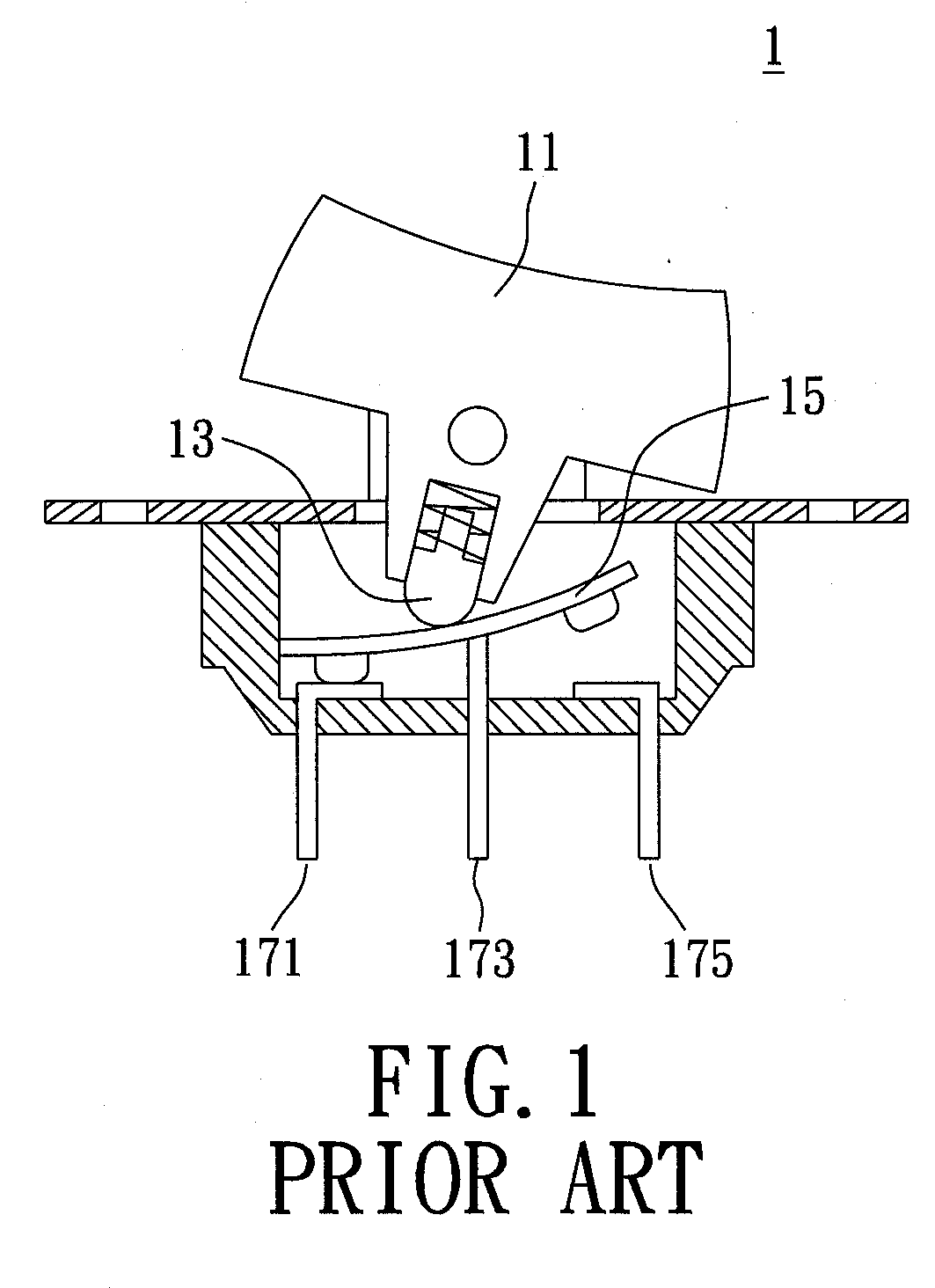
Figure 2 
Figure 3
Abstract
Description
BACKGROUND OF THE INVENTION
[0001] 1. Field of the Invention
[0002] The present invention relates to a switch module. In particular, the present invention relates to switch module having a surge absorber.
[0003] 2. Description of Related Art
[0004] A conventional switch module is shown in the FIG. 1. The conventional switch module 1 includes a press portion 11, a touching block 13, a conductive leverage 15, a first junction plate 171, a second junction plate 173 and a third junction plate 175. The touching block 13 is configured to push the conductive leverage 15 so that the first junction plate 171 could be in connection with or to be disconnected from the second junction plate 173. As such, a power could be switched on or off according to whether the press portion 11 is pressed. Meanwhile, the third junction plate 175 is connected with a lighting device for indicating.
[0005] The power surge and the voltage surge take place from time to time, and as the result the switch module 1 may be bur...