
Method for selectively triggering circuit breakers in the event of a short circuit

a circuit breaker and short circuit technology, applied in circuit breakers, circuit breakers for excess currents, emergency protective arrangements for limiting excess voltage/current, etc., can solve the problem of requiring a relatively large amount of additional circuit complexity, and achieve the effect of improving the accuracy of the calculated exponent, reducing computation complexity, and improving accuracy

Inactive Publication Date: 2011-05-12
SIEMENS AG
View PDF4 Cites 24 Cited by
  • Summary
  • Abstract
  • Description
  • Claims
  • Application Information

AI Technical Summary

Benefits of technology

At least one embodiment of the invention specifies a method which makes it possible to reliably detect whether a downstream circuit breaker is in this case ready to disconnect the relevant circuit in the event of a short.
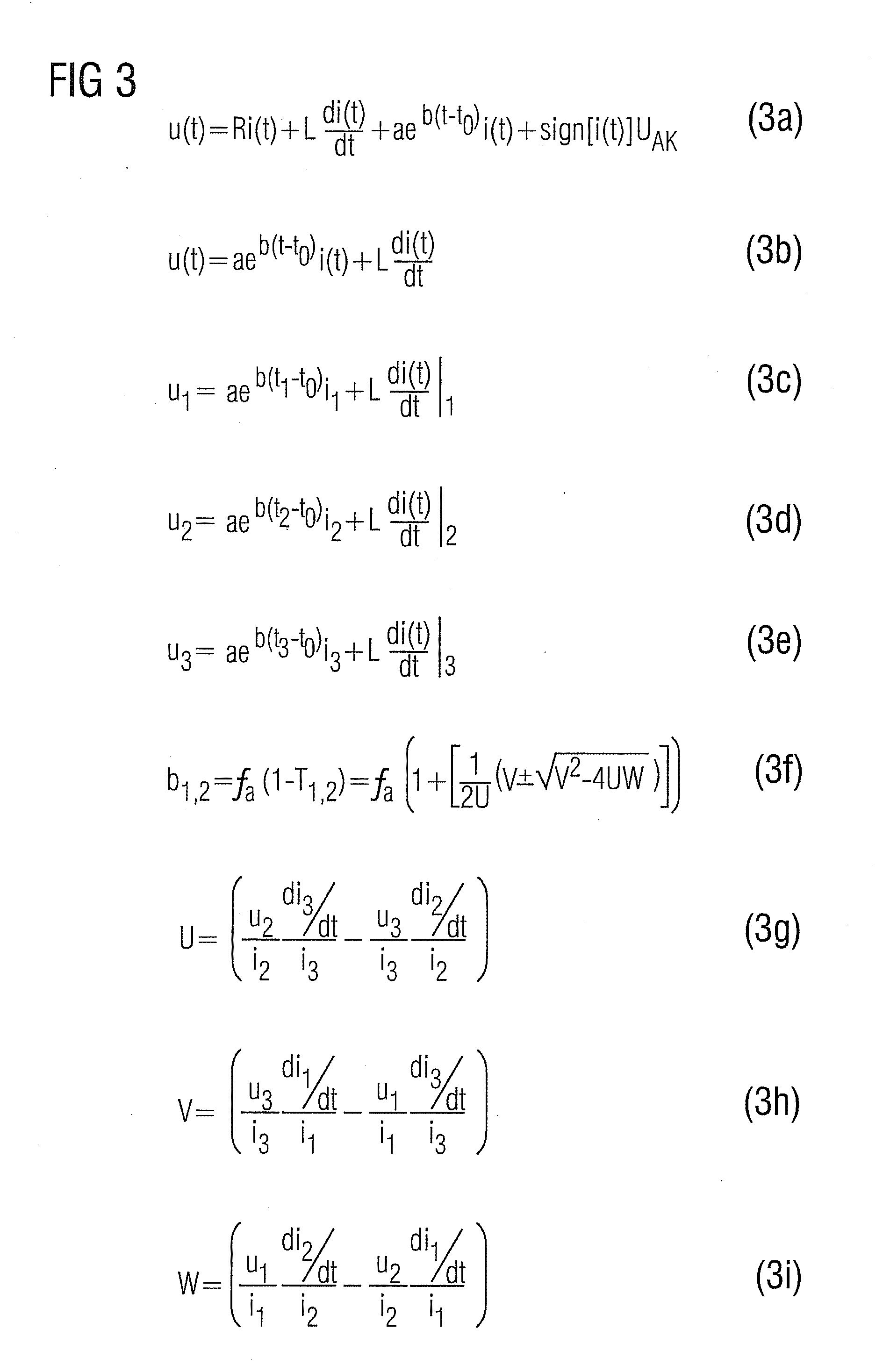
The accuracy can be improved with the computation complexity being reduced if, in the event of a short, that component of the inductance and of the resistance of the short-circuit loop which is constant over time is calculated for the sample values occurring before the exponential profile, and the inductance determined in this way and the resistance are used to correct the output-side voltage during the exponential profile as a result of the switching arc. The constant inductance and the constant component of the resistance of the short-circuit loop are therefore determined with the aid of the sample values before the exponential profile, in order in this way to correct the output-side measured voltage, and thus to improve the accuracy of the calculated exponent.

Problems solved by technology

However, this requires a relatively large amount of additional circuit complexity.

Method used


Image

  • Method for selectively triggering circuit breakers in the event of a short circuit
  • Method for selectively triggering circuit breakers in the event of a short circuit
  • Method for selectively triggering circuit breakers in the event of a short circuit

Examples


Embodiment Construction

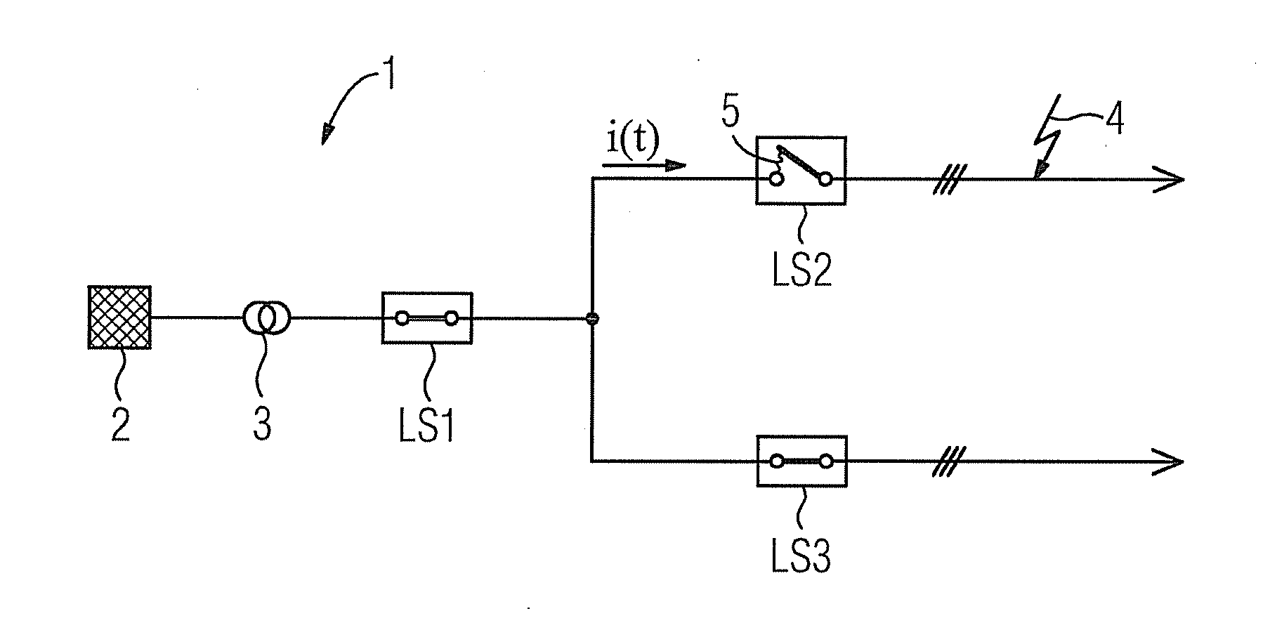
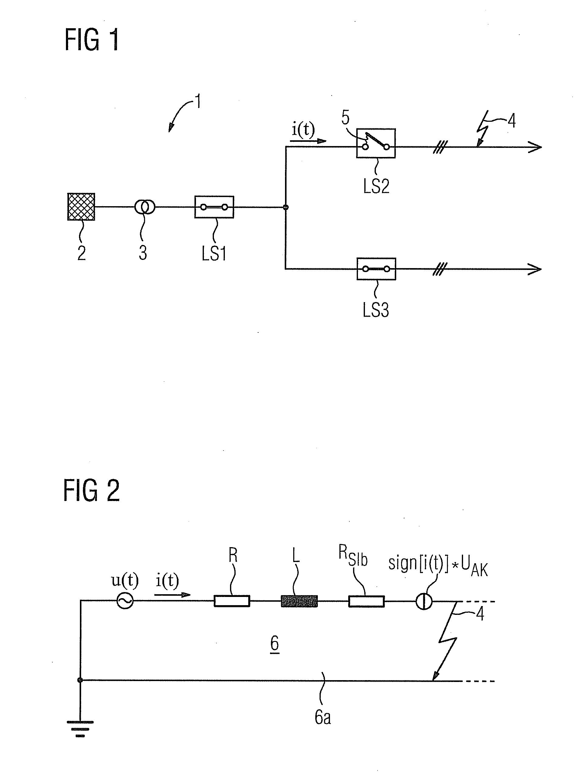
FIG. 1 shows a current feed 1 having an electrical power supply system 2 and a transformer 3. FIG. 1 also shows a circuit arrangement having a plurality of circuit breakers, in this case with three circuit breakers LS1, LS2, LS3 which are current-limiting low-voltage circuit breakers, which have very short disconnection times. The current feed 1 is first of all followed by the circuit breaker LS1 (close to the feed), which is arranged upstream of the two circuit breakers LS2, LS3, which are in this case disconnected in parallel. The two circuit breakers LS2, LS3 are connected downstream from the circuit breaker LS1, in each case seen from the current feed 1. The circuit breakers LS2, LS3 could, of course, also be connected one behind the other in series.

The large arrow on the right in FIG. 1 indicates that there is a short 4 downstream from the circuit breaker LS2, wherein the circuit breaker LS2 is closest to the short 4. FIG. 1 also shows that the circuit breaker LS2 (tripped, for...


PUM


Abstract

A method is disclosed for selectively triggering circuit breakers in the event of a short circuit, wherein an upstream circuit breaker and at least one downstream circuit breaker on the output side are provided. In at least one embodiment, the upstream circuit breaker monitors as to whether the or one of the downstream circuit breakers is already in the process of opening the switch contacts thereof to interrupt the circuit on the output side, while forming a switch arc. In order to reliably determine whether a downstream circuit breaker is already in the process of opening, according to at least one embodiment of the invention the upstream circuit breaker, so as to detect a switch arc on the output side, checks whether the ohmic resistance of the short circuit loop produced by a short circuit has an exponential curve over time in that an exponent is continually computed and based on the computer exponent the switch arc is determined if the computed exponent exceeds a threshold.

Description

FIELDAt least one embodiment of the invention generally relates to a method for selective tripping of circuit breakers, in particular of low-voltage circuit breakers, in the event of a short.BACKGROUNDIt is known for circuit breakers to be connected in series, wherein the circuit breaker which is arranged immediately downstream from the current feed is generally followed on the load side by a plurality of circuit breakers. It is also known for circuit breakers to be tripped selectively in the event of a short. In this case, selectively means that that circuit breaker is in each case tripped which is located closest to the location of the short, seen from the current feed, as a result of which no more loads than those which are unavoidable are affected by the disconnection. In order to achieve this, the mutual upstream and downstream circuit breakers can be the subject of current and time grading, in which case the circuit breaker close to the feed has longer disconnection times than...

Claims


Application Information

Patent Timeline
Patent Type & Authority Applications(United States)
IPC IPC(8): H02H7/26
CPCH02H7/30H02H1/0015
Inventor MEYER, JOERGSCHEGNER, PETER
Owner SIEMENS AG
Learn More