

Multiband DRC system and method for controlling the same
a drc system and multi-band technology, applied in the direction of transducer details, electrical transducers, electrical apparatus, etc., can solve the problems of insufficient reproduction of audio signals in high frequency bands, poor low frequency reproduction capability of speakers with a small diameter, and relatively small loudness of input signals in one frequency band, so as to increase the overall loudness of output signals
- Summary
- Abstract
- Description
- Claims
- Application Information
AI Technical Summary
Benefits of technology
Problems solved by technology
Method used
Image

Examples
first embodiment
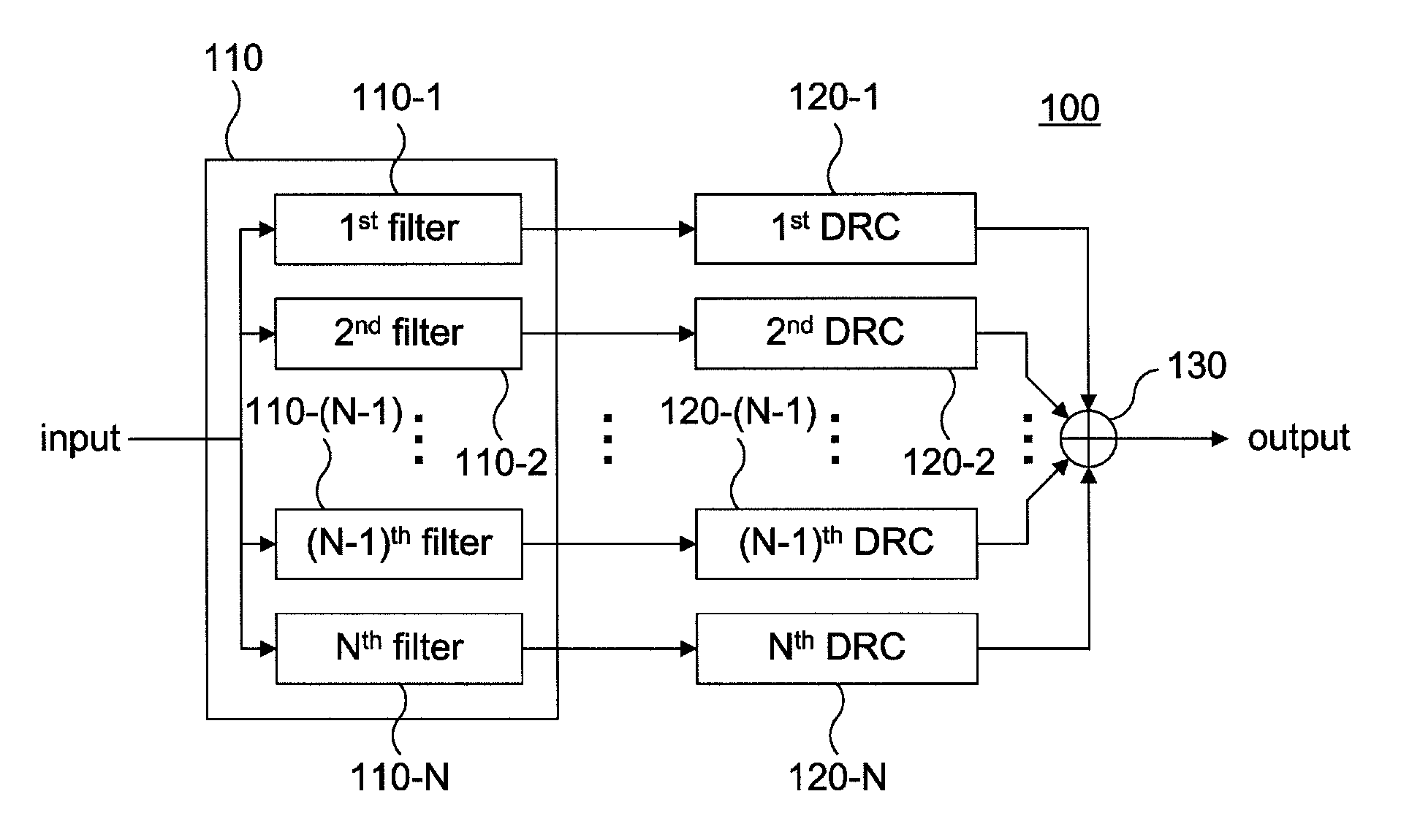
[0044]FIG. 3 is a block diagram exemplifying a multiband DRC system in accordance with the present invention.
[0045]Referring to FIG. 3, the multiband DRC system 100 in accordance with the first embodiment of the present invention comprises a filtering unit 110, a first DRC 120-1 though an Nth DRC 120-N and an adder 130.
[0046]In addition, the filtering unit 110 comprises a first filter 110-1 through an Nth filter 110-N.
[0047]The filtering unit 110 divides a digital audio signal into a first band audio signal through an Nth band audio signal according to (N−1) crossover frequencies.
[0048]The filtering unit 110 includes the first filter 110-1 though the Nth filter 110-N for dividing the digital audio signal into the first band audio signal through the Nth band audio signal according to the (N−1) crossover frequencies which are selected according to a target THD (Total Harmonic Distortion). The target THD and the crossover frequency will be described later with reference to FIG. 4.
[0049...
second embodiment
[0066]FIG. 8 is a block diagram exemplifying a multiband DRC system in accordance with the present invention.
[0067]The multiband DRC system in accordance with the second embodiment of the present invention shown in FIG. 8 is identical to that of FIG. 4 except a post DRC 140. Therefore, only the post DRC 140 will be described in detail and detailed description of other components will be omitted.
[0068]The post DRC 140 dynamically compresses the output signal of the adder 130.
[0069]Referring to FIG. 7, the output signal of the adder 130 widely distributed along the entire bands. However, an amplitude of the output signal is slightly increased near the crossover frequency.
[0070]As the first filter 110-1 and the second filter 110-2 overlap each other, the output signals are also overlapped with each other resulting in a partial distortion.
[0071]When the output signal of the adder 130 is compressed through the post DRC 140, the amplitude thereof may be limited near the crossover frequenc...
third embodiment
[0079]A multiband DRC system in accordance with the present invention is described hereinafter in more detail.
[0080]FIG. 11 is a block diagram exemplifying a multiband DRC system in accordance with a third embodiment of the present invention.
[0081]Referring to FIG. 11, the multiband DRC system 100 in accordance with the third embodiment of the present invention comprises a filtering unit 110, a first DRC 120-1 though an Nth DRC 120-N, an adder 130 and a gain controller 200.
[0082]In addition, the filtering unit 110 comprises a first filter 110-1 through an Nth filter 110-N.
[0083]The filtering unit 110 divides a digital audio signal into a first band audio signal through an Nth band audio signal according to (N−1) crossover frequencies.
[0084]The first DRC 120-1 through the Nth DRC 120-N dynamically compress output signals of the filtering unit 110, i.e., the first band audio signal through the Nth band audio signal, respectively.
[0085]The gain controller 200 controls gains of the firs...
PUM
 Abstract
Description
Claims
Application Information