Multistage gas furnace having split manifold

a gas furnace and manifold technology, applied in the field of climate control apparatus, can solve the problems of limited operating range, modulating furnace system, and low heat load requirements in many commercial buildings

Inactive Publication Date: 2011-05-12
CARRIER CORP
View PDF22 Cites 11 Cited by
  • Summary
  • Abstract
  • Description
  • Claims
  • Application Information

AI Technical Summary

Benefits of technology

[0004]A heating apparatus for a heat exchanger system includes a manifold having a plurality of burners, a shutoff valve, a first controller and a second controller. The shutoff valve divides the manifold into a first manifold portion and a second manifold portion. The first controller selectively controls the communication of a fluid within the manifold. The second controller selectively actuates the shutoff valve between a first position and a second position to control a firing rate of the plurality of burners.

Problems solved by technology

Conventional gas furnaces typically provide a limited operating range such that low heat load requirements are not satisfied in many commercial buildings.
Modulating furnace systems are also known but have also not effectively satisfied low heat loads that are often required in commercial buildings.

Method used


Image

  • Multistage gas furnace having split manifold
  • Multistage gas furnace having split manifold
  • Multistage gas furnace having split manifold

Examples


Embodiment Construction

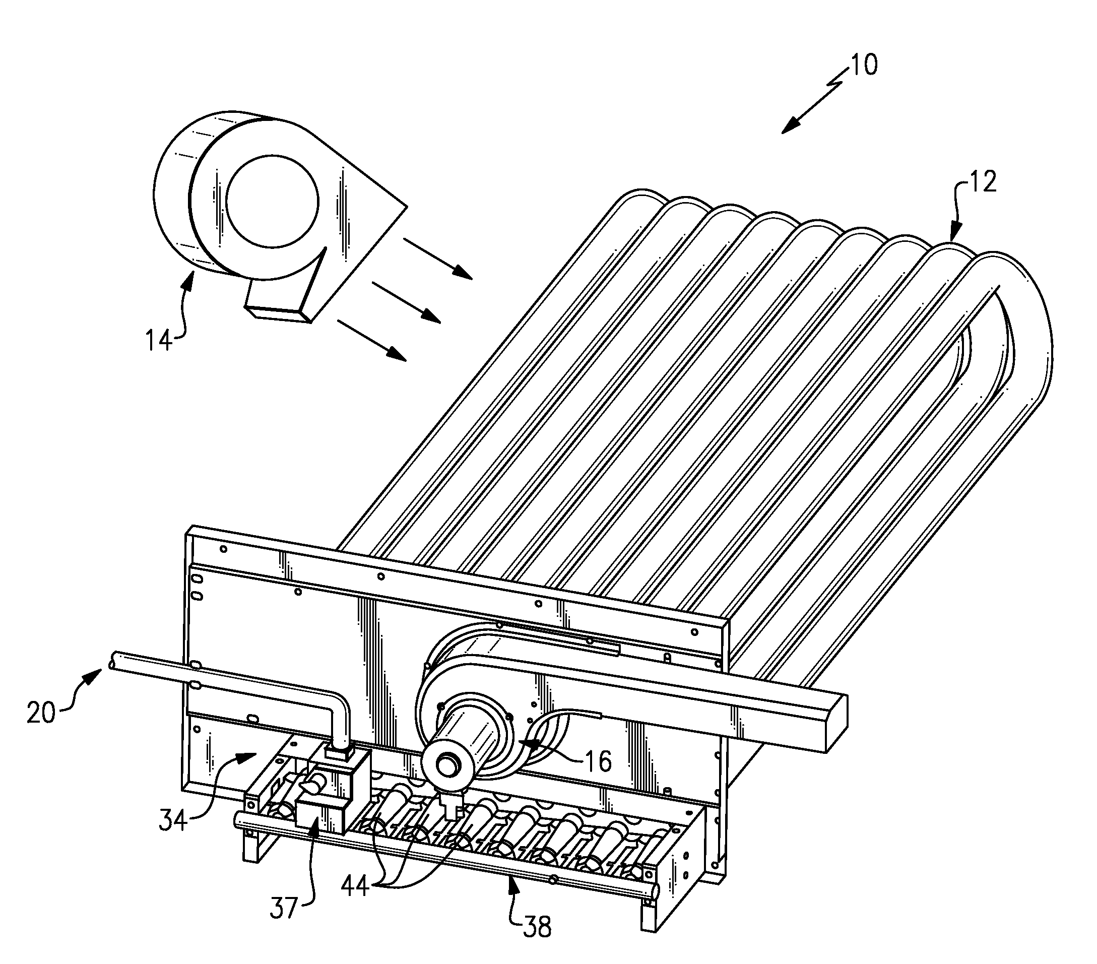
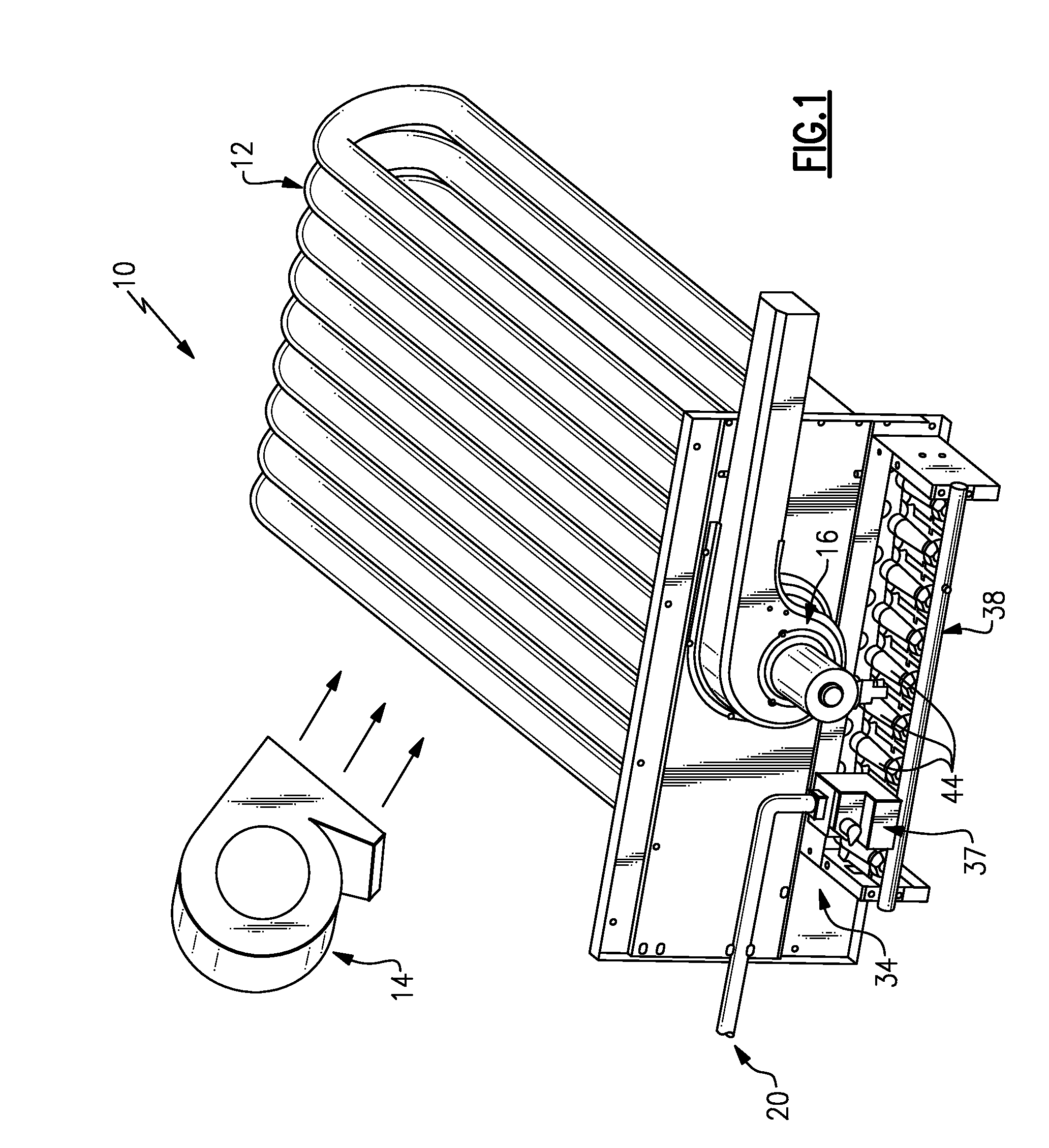
[0011]FIG. 1 illustrates an example heat exchanger system 10 for residential or commercial applications. In one example, the heat exchanger system 10 is a gas furnace. In another example, the heat exchanger system 10 is a gas furnace having multiple heating stages. It should be understood that the description and example illustrations described herein are not limited to a gas furnace. That is, this disclosure is applicable to any type of heat exchanger system.

[0012]The example heat exchanger system 10 includes a heat exchanger 12, a circulating air fan 14, a combustion air fan 16, a main gas valve (MGV) 37 and a heating apparatus 34. In one example, the heat exchanger system 10 is a gas furnace rooftop system. The heating apparatus 34 provides a desired level of heat to an interior space. The heating apparatus 34 includes a gas manifold 38 and a plurality of burners 44. A fluid, such as a gas, is communicated through a fluid supply pipe 20, to the MGV 37, and is further communicated...


PUM


Abstract

A heating apparatus for a heat exchanger system includes a manifold having a plurality of burners, a shutoff valve, a first controller and a second controller. The shutoff valve divides the manifold into a first manifold portion and a second manifold portion. The first controller selectively controls the communication of a fluid within the manifold. The second controller selectively actuates the shutoff valve between a first position and a second position to control a firing rate of the plurality of burners.

Description

CROSS-REFERENCE TO RELATED APPLICATIONS[0001]This application claims priority to U.S. Provisional Application No. 61 / 086,887, filed Aug. 7, 2008.BACKGROUND OF THE DISCLOSURE[0002]This disclosure relates to a climate control apparatus, and more particularly to a gas furnace.[0003]Gas furnaces are used to heat residential dwellings and commercial buildings. Heated air is provided to an interior space of the residential dwelling or the commercial building through a plenum. Gas furnaces typically include a main gas valve that communicates gas into a manifold having a plurality of burners for igniting the gas. A desirable feature of a gas furnace is to match the output capacity of the furnace to the heating load required by the interior space of a residential dwelling or commercial building. Commercial buildings, in particular, can benefit from relatively low amounts of heating. Conventional gas furnaces typically provide a limited operating range such that low heat load requirements are...

Claims


Application Information

Patent Timeline
Patent Type & Authority Applications(United States)
IPC IPC(8): F23D14/46F23N1/00F23K5/00F23Q5/00F23N5/00
CPCF23D23/00F23D2900/14641F23N2041/04F23N2037/02F23N1/002F23N2237/02F23N2241/04
Inventor VIDETO, BRIAN D.BUSSJAGER, RUDDY C.
Owner CARRIER CORP
Why Eureka
Try Eureka