Printed circuit board terminal and printed circuit board connector having the same

a technology of printed circuit board and connector, which is applied in the direction of printed circuit parts, coupling contact members, contact member manufacturing, etc., can solve the problems of difficult formation of through holes and soldering, difficult to secure the strength of the printed circuit board between through holes, and narrow interval between through holes provided in the printed circuit board. , to achieve the effect of reducing the size of the through hole provided in reducing the length of the insertion portion of the printed circuit board, and reducing the length of th

Active Publication Date: 2011-05-12
SUMITOMO WIRING SYST LTD
View PDF11 Cites 19 Cited by
  • Summary
  • Abstract
  • Description
  • Claims
  • Application Information

AI Technical Summary

Benefits of technology

[0010]In view of the above circumstances, the present invention provides a printed circuit board terminal having a new configuration, in which the printed circuit board terminal is made of a metal wire rod and is insertable into a small-diameter through hole, and sufficient solder wettability can be achieved without after-plating.
[0013]According to the aspect of the present invention, the dimension in the long side direction of the printed circuit board terminal is reduced at the insertion portion, which is inserted into the through hole. Accordingly, the size of the through hole provided in the printed circuit board can be reduced. As a result, while the other end portion, having a rectangle cross-section, on the side opposite to the insertion portion is connectable to another connector, an amount of necessary space on the printed circuit board can be reduced.
[0014]In addition, since the insertion portion is formed by cutting away only the marginal portion at one end in the width direction of the cut wire rod having the rectangle cross-section, the plated layer previously provided on the surface of the metal wire rod can remain on the three side surfaces of the insertion portion, other than the surface at the cut away side in the width direction. Accordingly, by taking advantage of the plated layer provided on the three surfaces, the printed circuit board terminal in which the solder wettability at the insertion portion is sufficiently secured, can be provided cost effectively. In particular, even in the lead-free solder, etc., that requires an improved solder wettability, a sufficient solder wick can be realized without performing after-plating.
[0016]In the printed circuit board terminal according to this aspect of the present invention, since the printed circuit board terminal according to the aspect of the present invention is used for any terminal of the plurality of printed circuit board terminals attached to the connector housing, the size of the through hole can be reduced at a necessary portion in accordance with the requirement of circuit wiring, and thus a space on the printed circuit board can be secured. In addition, by utilizing the printed circuit board terminal according to the aspect of the present invention to conform the size of the insertion portion to that of the other printed circuit board terminal, the through holes can be universal.
[0018]According to this aspect of the present invention, when the printed circuit board connector includes terminals having various width dimensions (shapes of cross-section), by utilizing the printed circuit board terminal according to the aspect of the present invention as a printed circuit board terminal having a rectangle cross-section with a long width dimension, the width dimension of the insertion portion can be reduced. Accordingly, even if the printed circuit board connector includes both a terminal having a rectangle cross-section and a terminal having a square cross-section, the insertion portions can be uniform in size. Therefore, the through holes provided in the printed circuit board can have a universal shape, regardless of the width dimension of the terminals. Thus, formation of an elongate through hole is not required and thus the cost can be reduced.
[0023]According to the aspects of the present invention, an insertion portion to be inserted into a through hole is made by cutting away only the marginal portion at one side in a width direction of a cut wire rod, which has a rectangle cross-section and an entire surface of which is covered by a plated layer. Accordingly, a dimension in the long side direction of the insertion portion of the printed circuit board terminal can be reduced, and thus the size of the through hole provided in the printed circuit board can be reduced. As a result, the space on the printed circuit board can be used efficiently. Further, since the plated layer remains on the three surfaces other than the surface cut away at the insertion portion, solder wettability is secured and an after-plating process is not required. Accordingly, a manufacturing cost efficiency can be improved.

Problems solved by technology

However, when the pitch of the printed circuit board terminals is narrowed, the interval between the through holes provided in the printed circuit board also becomes narrow, and formation of the through holes and soldering become difficult.
Further, it is difficult to secure the strength of the printed circuit board between the through holes.
Therefore, a solder wick may become poor.
However, the after-plating process makes the manufacturing process of the printed circuit board terminal complicated, and increases the cost.

Method used


Image

  • Printed circuit board terminal and printed circuit board connector having the same
  • Printed circuit board terminal and printed circuit board connector having the same
  • Printed circuit board terminal and printed circuit board connector having the same

Examples


Embodiment Construction

[0034]The particulars shown herein are by way of example and for purposes of illustrative discussion of the embodiments of the present invention only and are presented in the cause of providing what is believed to be the most useful and readily understood description of the principles and conceptual aspects of the present invention. In this regard, no attempt is made to show structural details of the present invention in more detail than is necessary for the fundamental understanding of the present invention, the description is taken with the drawings making apparent to those skilled in the art how the forms of the present invention may be embodied in practice.

[0035]Embodiments of the present invention will be described hereinafter with reference to the drawings.

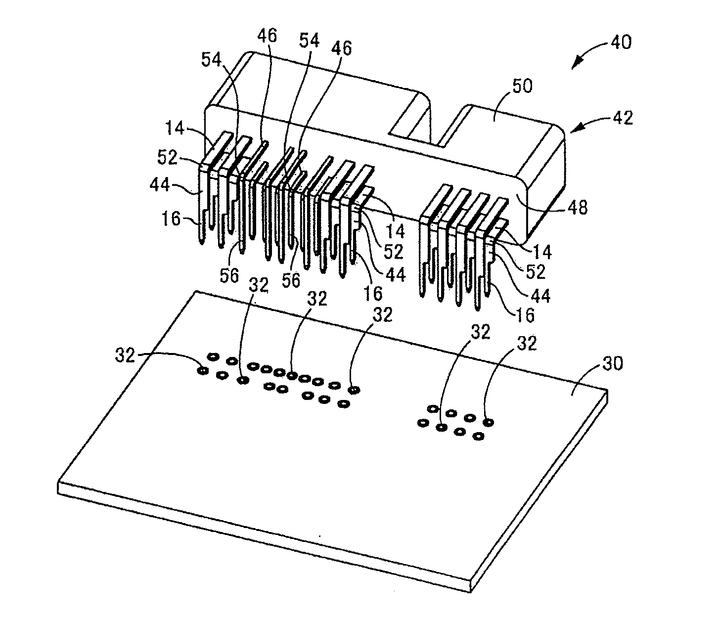
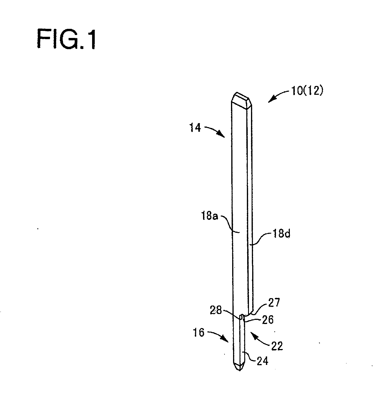
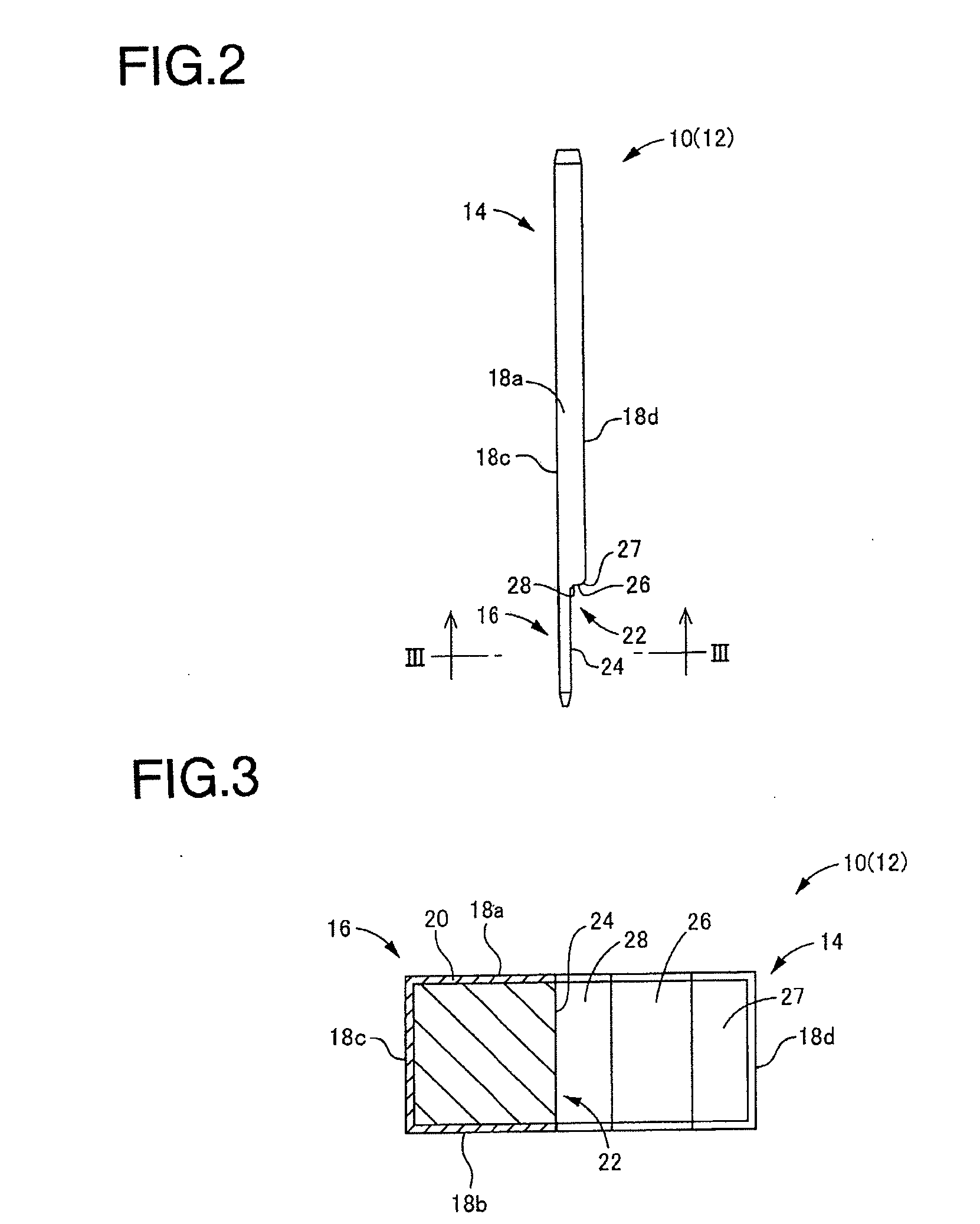
[0036]FIGS. 1-3 show a printed circuit board terminal 10 according to an embodiment of the present invention related to a printed circuit board terminal. The printed circuit board terminal 10 is made of a cut wire rod 12, wh...


PUM


Abstract

A printed circuit board terminal includes a rectangular metal wire rod having a substantially rectangle cross-section. One longitudinal end portion of the printed circuit board terminal includes an insertion portion that is configured to be inserted into a through hole provided in a printed circuit board and soldered. A conducting metal plated layer is provided on an entire surface of the rectangular metal wire rod. One marginal portion of the insertion portion, which faces a long side direction of the rectangle cross-section, is removed to reduce a dimension in the long side direction corresponding to a width direction.

Description

CROSS-REFERENCE TO RELATED APPLICATIONS[0001]The present application claims priority under 35 U.S.C. §119 of Japanese Application No. 2009-258249, filed on Nov. 11, 2009, the disclosure of which is expressly incorporated by reference herein in its entirety.BACKGROUND OF THE INVENTION[0002]1. Field of the Invention[0003]The present invention relates to a printed circuit board terminal, made of a metal wire rod, which is inserted into a through hole in a printed circuit board and is soldered to an electrically-conducting path, and to a connector having the printed circuit board terminal.[0004]2. Description of Related Art[0005]Conventionally, a printed circuit board having many relays, fuses, and the like, to distribute electric power to various electric components, is used as an electric junction box mounted on a vehicle. In such a printed circuit board, a printed circuit board terminal is used to electrically connect an electrically-conducting path on the printed circuit board to an...

Claims


Application Information

Patent Timeline
Patent Type & Authority Applications(United States)
IPC IPC(8): H01R12/00H05K1/11
CPCH01R12/585H01R13/03H01R43/16H05K2201/10863H05K2201/10189H05K2201/10848H05K3/308
Inventor GOTO, HIDEKI
Owner SUMITOMO WIRING SYST LTD
Why Eureka
Try Eureka