Device for attaching an aircraft engine comprising a thrust force take-up device with a compact design

a technology for aircraft engines and thrust forces, applied in the direction of machine supports, transportation and packaging, other domestic objects, etc., can solve the problems of complex assembly, requiring special equipment, and bringing them together

Active Publication Date: 2011-05-19
AIRBUS OPERATIONS (SAS)
View PDF9 Cites 32 Cited by
  • Summary
  • Abstract
  • Description
  • Claims
  • Application Information

AI Technical Summary

Benefits of technology

[0016]Thus, the engine is attached to the box and forces are taken up at two attachment points, thereby avoiding the need to use special equipment for the assembly. Moreover, the spreader beam stop attached to the strut is eliminated.
[0017]In other words, the attachment device is simplified by using lateral fittings as a spreader beam stop, thereby enabling the stops attached to the box to be eliminated.
[0018]Advantageously, the failsafe function of the mechanical connection between the spreader beam and the rear attachment is ensured by doubling the connection fitting.
[0019]The two connection fittings are fitted, thereby enabling the bulk of the device to be reduced.
[0020]The attachment device provides the advantage of enabling easier disassembly of the engine, since there are only two interface points between the engine and the box.

Problems solved by technology

This tilting makes the assembly complex and requires special equipment to be used to enable such an attachment.
Bringing them together then limits the possibility of using special equipment.
However, in certain applications, the box has a relatively low width, not enabling such stops to be attached.

Method used


Image

  • Device for attaching an aircraft engine comprising a thrust force take-up device with a compact design
  • Device for attaching an aircraft engine comprising a thrust force take-up device with a compact design
  • Device for attaching an aircraft engine comprising a thrust force take-up device with a compact design

Examples


first embodiment

[0023]In a first embodiment, the external fitting comprises a hollow body and a plate extending toward the front of said casing and the internal fitting comprises a body housed in the hollow body of the external fitting and comprising a plate extending toward the front from the body, said plate being parallel to the first plate, in which the two plates form a clevis mounting to which the spreader beam is mechanically connected.

[0024]The spreader beam can then comprise a first and a third portion forming a clevis mounting and surrounding the clevis mounting of the connection fitting and a second portion inserted between the first and the third portions, in which said second portion penetrates the clevis mounting of the connection fitting.

second embodiment

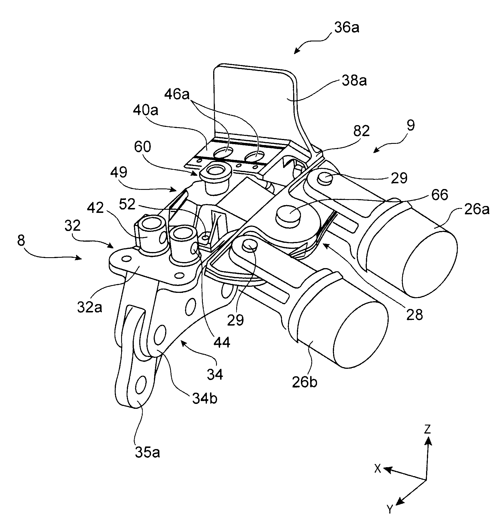
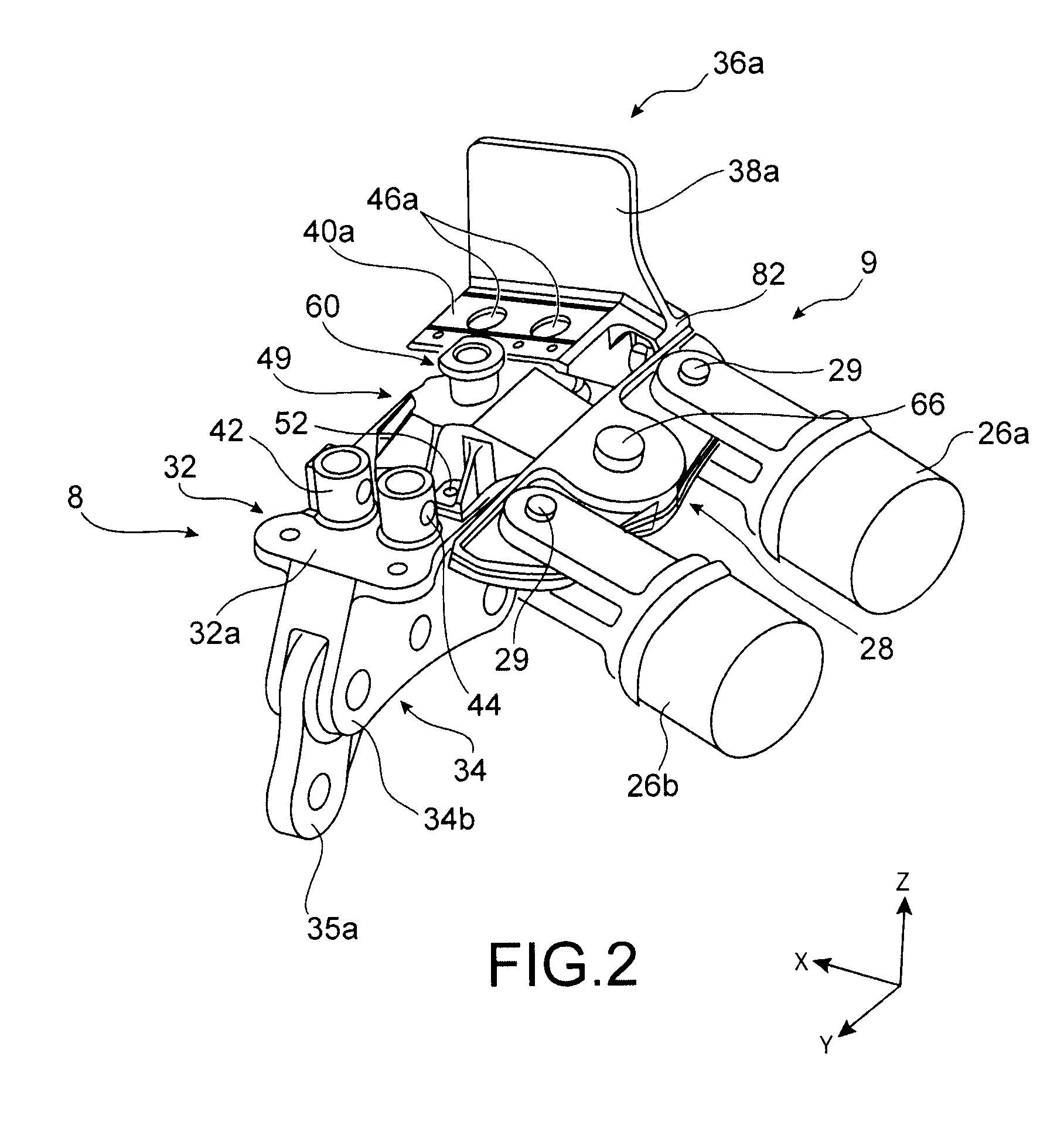
[0025]In a second embodiment, the external fitting comprises a body formed by a casing without a base, and a clevis mounting extends toward the front from a front wall of the casing; said front wall comprises a hole enabling communication between the inside of the casing and the space between the branches of the clevis mounting, and the internal fitting comprises a body housed in the body of the external fitting and a plate passing through the hole of the front wall and housed between the branches of the clevis mounting; the spreader beam comprises two portions forming a clevis mounting; said clevis mounting receives the plate of the internal fitting and is received in the clevis mounting of the external fitting.

[0026]For example, the bodies of the external and internal fittings each comprise means for peripheral attachment to the rear engine attachment by tension bolts, in which the means for attaching the internal fitting are clamped between the means for attaching the external fi...


PUM


Abstract

An aircraft engine attachment device including a rigid structure and a mechanism attaching the engine on the rigid structure, the attachment mechanism including a rear engine attachment and a device for taking-up thrust forces generated by the engine. The rear engine attachment is attached to the rigid structure by two lateral fittings attached to the rigid structure. The force take-up device includes two connecting rods mechanically connected to a spreader beam by a mechanical connection, a connection fitting attached to the rear engine attachment and mechanically connected to the rigid structure by a thrust pin, the lateral fittings including a stop mechanism to limit pivoting of the spreader beam if a connecting rod breaks and ensuring transmission of thrust forces to the rigid structure.

Description

TECHNICAL FIELD AND PRIOR ART[0001]This invention relates in general to a device for attaching an aircraft engine, for example intended to be inserted between an aircraft wing and the engine concerned, an engine assembly including such an attachment device, as well as an aircraft comprising at least one such attachment device.[0002]The invention can be used on any type of aircraft equipped with turbojets or turboprop engines.[0003]This type of attachment device, also called an attachment strut or “EMS” (for Engine Mounting Structure), can be used indifferently to suspend an engine below the wing of the aircraft, mount said engine above said same wing, or to attach said engine in the rear portion of the aircraft fuselage.[0004]Such an attachment device is indeed intended to form the connection interface between a turboshaft engine and a wing of the aircraft. It enables the forces generated by the associated turboshaft engine to be transmitted to the structure of said aircraft, and al...

Claims


Application Information

Patent Timeline
Patent Type & Authority Applications(United States)
IPC IPC(8): B64D27/02B64D27/26
CPCB64D27/26B64D2027/268B64D2027/264
Inventor GUILLET, EMMANUELMARTINOU, JEAN-MARCGARDES, PASCAL
Owner AIRBUS OPERATIONS (SAS)
Why Eureka
Try Eureka