Level shift circuit and switching power source apparatus

Active Publication Date: 2011-05-19
SANKEN ELECTRIC CO LTD
View PDF10 Cites 21 Cited by
  • Summary
  • Abstract
  • Description
  • Claims
  • Application Information

AI Technical Summary

Benefits of technology

[0023]There are two typical cases that a transient voltage dv/dt is applied to a level shift circuit. In the first case, a low-side switching element is OFF and a high-side switching element is turned on to shift 0 V to 420 V, or the high-side switching element is OFF and the low-side switching element is turned on to shift

Problems solved by technology

If this happens, the erroneously turned off high-side switching element causes a drop in an output voltage of a switching power source

Method used


Image

  • Level shift circuit and switching power source apparatus
  • Level shift circuit and switching power source apparatus
  • Level shift circuit and switching power source apparatus

Examples


Example

Embodiment 1

[0050]FIG. 4 is a circuit diagram illustrating a level shift circuit according to Embodiment 1 of the present invention. The level shift circuit has resistors R1 to R6, a pulse generator 10, transistors MN1, MN2, MN3, and MN4, and a flip-flop 12. The level shift circuit of Embodiment 1 is not provided with the filter circuit 26 of the related art of FIG. 2, and instead, is provided with the resistors R5 and R6 and transistors MN1 and MN2.

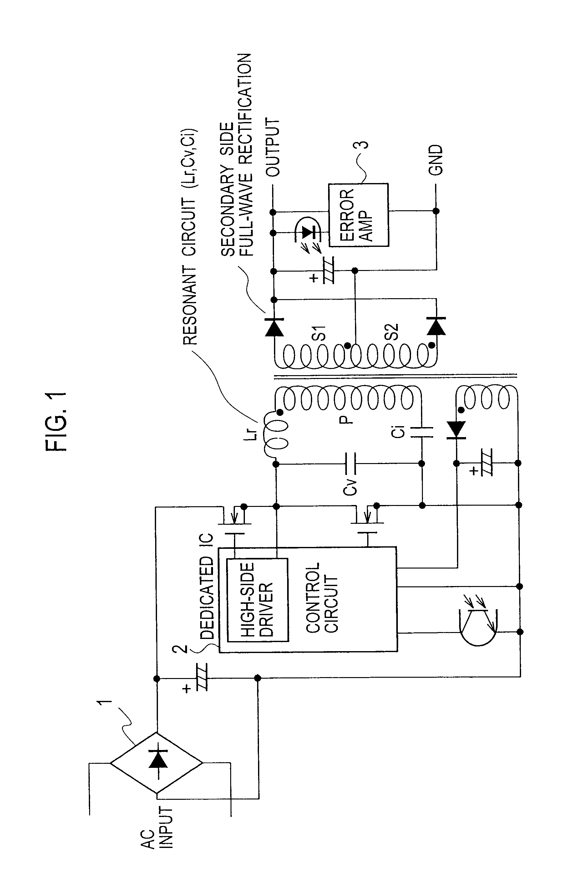
[0051]FIG. 5 is a circuit diagram illustrating a switching power source apparatus employing the level shift circuit of FIG. 4. The switching power source apparatus is a half-bridge, current-resonant switching power source apparatus having a high-side switching element 17a and a low-side switching element 18a. To control the high-side switching element 17a, the level shift circuit is arranged in a control circuit 2. The present invention is also applicable to a full-bridge switching power source apparatus.

[0052]In the switching power sour...

Example

Embodiment 2

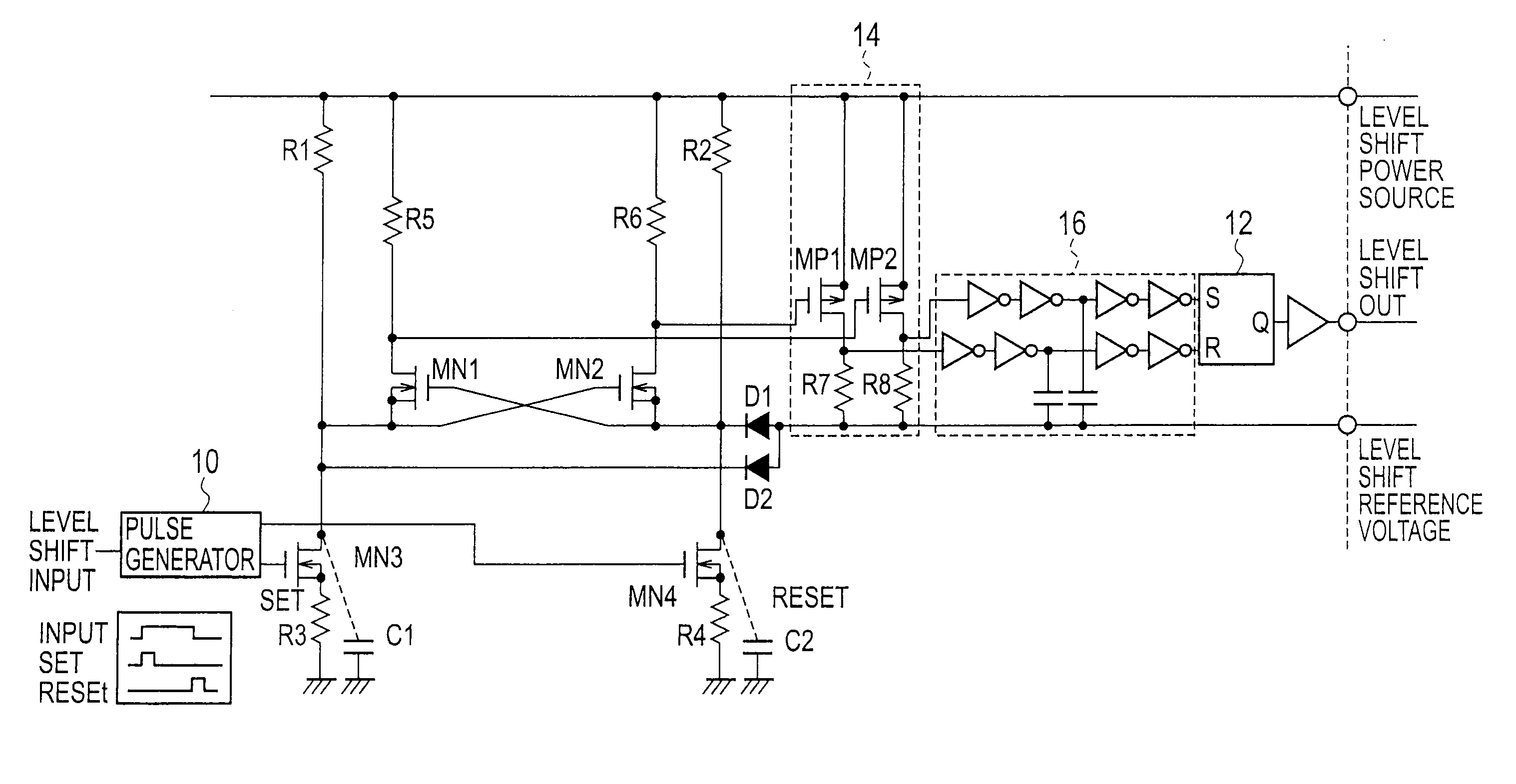
[0093]FIG. 9 is a circuit diagram illustrating a level shift circuit according to Embodiment 2 of the present invention. Embodiment 2 differs from Embodiment 1 illustrated in FIG. 4 in that Embodiment 2 additionally uses diodes D1 and D2, a buffer part 14, and a filter part 16. Like the level shift circuit of Embodiment 1, the level shift circuit of Embodiment 2 is used in a switching power source apparatus such as the one illustrated in FIG. 5.

[0094]The buffer part 14 has transistors MP1 and MP2 and resistors R7 and R8.

[0095]The transistor MP2 and resistor R8 correspond to the “first amplifier” stipulated in the claims and are arranged between a control part and a flip-flop 12, to amplify a set signal generated by the control part so that the set signal is detected by the flip-flop 12.

[0096]The transistor MP2 corresponds to the “first p-type MOSFET” stipulated in the claims and has a source connected to a level shift power source and a gate connected to a resistor R5, t...


PUM


Abstract

A level shift circuit includes a first resistor connected to a level shift power source, a first transistor having a drain connected to a second end of the first resistor and a source to the ground, a second resistor connected to the level shift power source, a second transistor having a drain connected to a second end of the second resistor and a source to the ground, a pulse generator controlling ON/OFF of the first and second transistors according to an input signal, a control part generating a set signal if the first transistor is ON, a reset signal if the second transistor is ON, and no signal if there is no voltage difference between a voltage at the drain of the first transistor and a voltage at the drain of the second transistor, and a flip-flop providing an output signal according to the set and reset signals.

Description

BACKGROUND OF THE INVENTION[0001]1. Field of the Invention[0002]The present invention relates to a level shift circuit used as an interface between circuits operating on different power source voltages and a switching power source apparatus employing the level shift circuit.[0003]2. Description of the Related Art[0004]A switching power source apparatus used for a flat panel display, which is strongly required to be thinner, is frequently of a half-bridge type with two switching elements and a current resonant type capable of reducing a switching loss. To miniaturize and thin the flat panel displays such as LCD TVs and other consumer appliances, switching power source apparatuses used with them are required to operate at higher frequencies with the use of smaller parts.[0005]The half-bridge switching power source apparatus employs two n-type MOSFETs and a level shift circuit to transfer a low-side control signal to a high side. When the switching power source apparatus is used with a...

Claims


Application Information

Patent Timeline
IPC IPC(8): H03L5/00
CPCH03K19/018521H03K19/017509H03K19/0185H03K19/018507H03K19/018514
Inventor KOIKE, KENGO
Owner SANKEN ELECTRIC CO LTD
Why Eureka
Try Eureka