Cleaner for inside of water tank

a technology for cleaning equipment and water tanks, applied in the direction of bends, machines/engines, transportation and packaging, etc., can solve the problems of cumbersome operation, difficult operation for children, and requiring experience, so as to achieve quick and efficient operation and ensure the smooth operation of suction operation tools

Active Publication Date: 2011-05-26
OGAWA SOICHI
View PDF20 Cites 1 Cited by
  • Summary
  • Abstract
  • Description
  • Claims
  • Application Information

AI Technical Summary

Benefits of technology

[0012]In accordance with each aspect of the present invention, in the cleaner for the inside of a water tank, by just gripping the suction pipe, whose main body portion is placed inside the water tank, with one hand and pressing the suction operation tool, a siphoning action can be established for the suction pipe, and anybody can simply and easily suck outside water-tank water together with waste material such as leftover food or fish excrement.
[0013]Furthermore, in accordance with the second aspect of the present invention, since the suction operation tool is connected so as to communicate with the interior of the water passage and is provided substantially parallel to the main body portion of the suction pipe, the operational direction of the suction operation tool coincides with the direction of suction of water by the suction pipe, and the operation of cleaning waste material such as leftover food or fish excrement can be carried out quickly and efficiently.
[0014]Moreover, in accordance with the third aspect of the present invention, since the suction operation tool is provided above the upper wall of the suction pipe, and the operation chamber thereof is positioned above the water passage within the suction pipe, fine foreign matter such as gravel that is sucked up together with the water-tank water within the suction pipe does not enter the interior of the operation chamber of the suction operation tool and bite into the seal ring, and smooth operation of the suction operation tool can be guaranteed.

Problems solved by technology

However, this conventional cleaner has the problem that when water is sucked into the suction pipe by utilizing a siphoning action, it is necessary for an operator to put the suction pipe into water-tank water of the water tank by gripping it and then carry out a repeated operation of vertical movement of the suction pipe in its longitudinal direction; this operation is not only cumbersome, but it also requires experience, and it is difficult for a child to carry out the operation.

Method used


Image

  • Cleaner for inside of water tank
  • Cleaner for inside of water tank
  • Cleaner for inside of water tank

Examples


embodiment 1

[0039]A first embodiment of the present invention is now explained by reference to FIGS. 1 to 6.

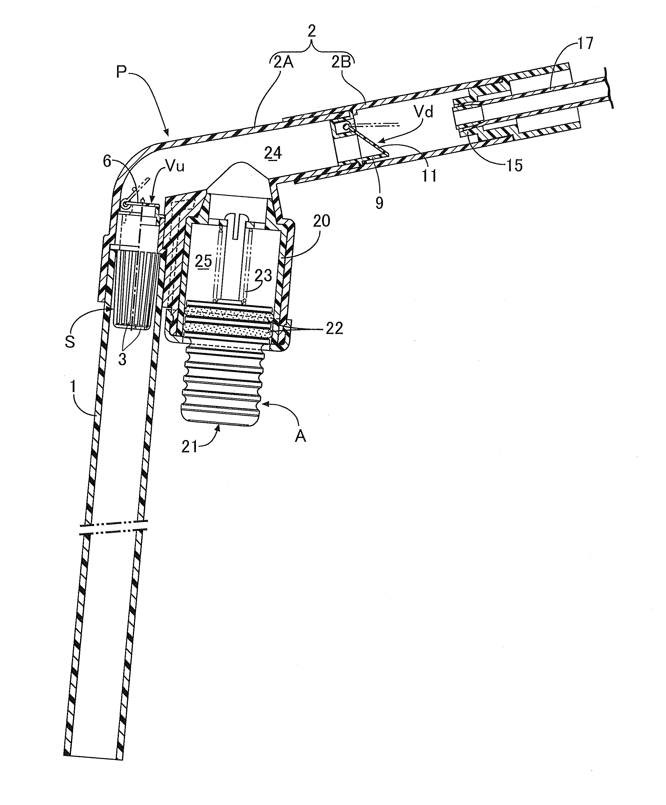
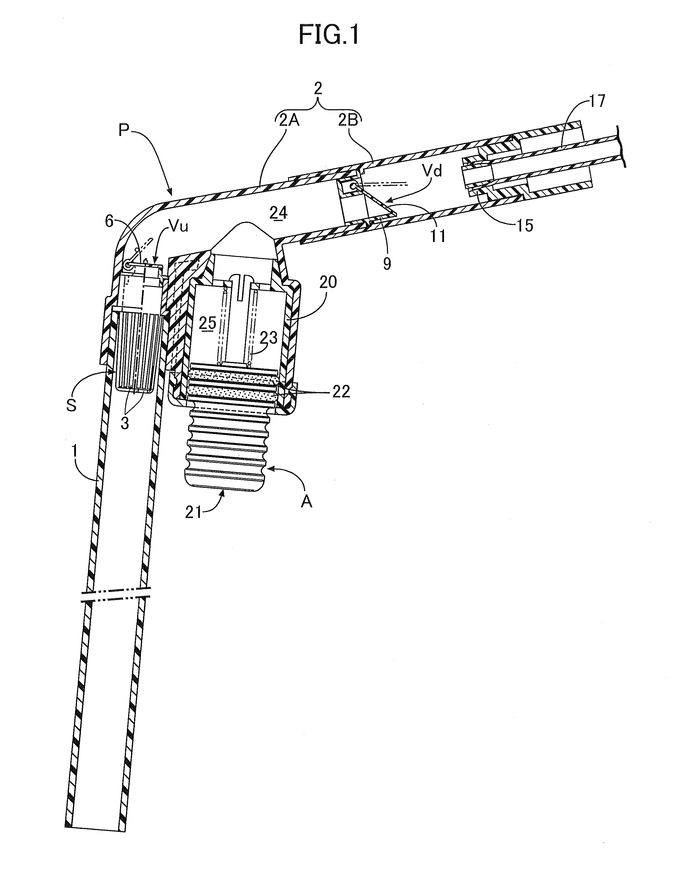
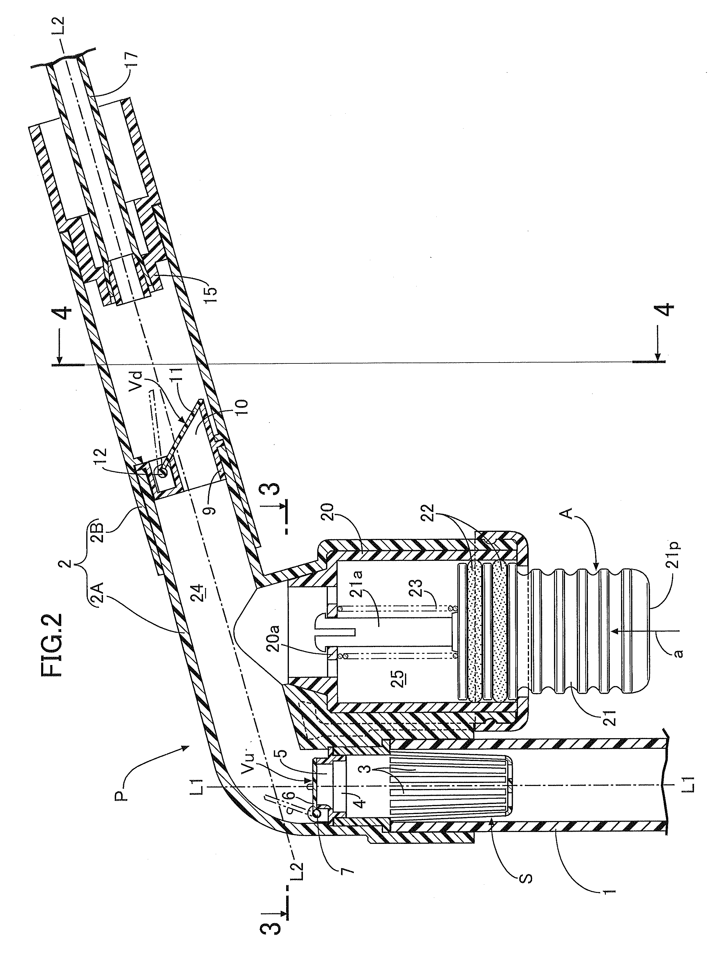
[0040]In FIGS. 1 to 5, a suction pipe P forming a main body part of a cleaner for the inside of a water tank is made with a transparent rigid synthetic resin material, and is formed in a dog-leg shape when viewed from the side from a straight cylindrical main body portion 1 that has an open extremity and is formed with a length that reaches to the bottom of a water tank V from the outside of the water tank V and a grip portion 2 bent so as to be communicatingly connected to the base end, that is, the downstream end, of the main body portion 1. The grip portion 2 is formed by removably and watertightly connecting an elbow pipe 2A and a straight pipe 2B. An angle formed by a central line L1 of the main body portion 1 and a central line L2 of the grip portion 2 is an obtuse angle, that is, about 105° , and this makes it difficult for the grip portion 2 to abut against an edge of the water ta...

embodiment 2

[0055]A second embodiment of the present invention is now explained by reference to FIGS. 7 and 8.

[0056]The second embodiment is different from the first embodiment in terms of the position at which a suction operation tool A is mounted on a suction pipe P, as shown in FIG. 7, the suction operation tool A being provided in an upper part of the suction pipe P, that is, an upper wall of a grip portion 2. This suction operation tool A has the same structure as that of the first embodiment; an operation tube 20 is formed integrally with an upper face of the grip portion 2, this operation tube 20 extends upward substantially parallel to the main body portion 1, and an operation chamber 25 within the operation tube 20 is at a position outside and above a water passage 24 within the suction pipe P and communicates with the water passage 24. A press button 21 is slidably fitted via a seal ring 22 into the operation tube 20 from the open upper end thereof, and a press face 21p is formed on a...

modified example of embodiment 2

[0063]A modified example of the second embodiment is now explained by reference to FIG. 9.

[0064]This modified example is a case in which a suction operation tool A having the same structure as that of the second embodiment is provided at the upper end of a linear main body portion 1 of a suction pipe P; an operation chamber 25 is at a position outside and above a water passage 24 of the suction pipe P, and the same operation and effects as those of the second embodiment can be exhibited.


PUM


Abstract

A cleaner for the inside of a water tank utilizing a siphoning action is provided, in which the interior of a water passage (24) between an upstream-side one-way valve (Vu) and a downstream-side one-way valve (Vd) is pressurized or depressurized by a pressing operation of a suction operation tool (A) provided in a bent connecting part between a main body portion (1) and a grip portion (2) of a suction pipe (P), and water-tank water of the main body portion (1) is sucked into the suction pipe (P). This enables waste material such as leftover food within water-tank water to be sucked up together with dirty water by a very simple operation.

Description

TECHNICAL FILED[0001]The present invention relates to an improvement of a cleaner for the inside of a water tank in which water-tank water inside a water tank for breeding aquarium fish, in particular dirty water-tank water in a bottom part inside the water tank, can be sucked up and drained outside the water tank.BACKGROUND ART[0002]Conventionally, when breeding and rearing aquarium fish such as goldfish, tropical fish, or marine fish inside a water tank, the water tank is provided with an internal or external filter device equipped with an air pump or a submersible pump, and water-tank water inside the water tank is filtered by forcibly circulating it to the filter device by driving the pump, but since it is impossible to obtain water quality that is necessary and sufficient for breeding and rearing aquarium fish just by filtration with such a filter device, it is necessary to regularly change water-tank water inside the water tank. A cleaner for the inside of a water tank in whic...

Claims


Application Information

Patent Timeline
Patent Type & Authority Applications(United States)
IPC IPC(8): F16L43/00
CPCF04F10/00A01K61/003A01K63/10Y10T137/86019Y10T137/2883Y10T137/2713Y10T137/2747Y10T137/2829Y10T137/86099A01K63/04B08B9/08
Inventor OGAWA, SOICHIYOSHIDA, YUTAKA
Owner OGAWA SOICHI
Why Eureka
Try Eureka