
Method and device for grinding a continuous casting product

a technology of continuous casting and product, which is applied in the direction of work treatment devices, grinding machines, metal rolling, etc., can solve the problems of large and heavy construction of grinding tables, prone to undesirable vibrations, and prone to bending

Inactive Publication Date: 2014-12-02
SMS LOGISTIKSYST
View PDF24 Cites 1 Cited by
  • Summary
  • Abstract
  • Description
  • Claims
  • Application Information

AI Technical Summary

Benefits of technology

[0011]The object of the invention is therefore to create a method and an associated apparatus with which it is possible to minimize the bending of the continuously cast product, in particular of the slabs, using a relatively light construction. The object is also to optimize the quality of the grinding processing. Furthermore, the object is to ensure that the grinding of the continuously cast product can be carried out efficiently and quickly so the grinding processing can be cost-effective. Furthermore, the aim is to design the method and the apparatus such that a removal of the grinding chips can be carried out in an improved manner. This is designed in particular to reduce the deposit of chips on the apparatus.SUMMARY OF THE INVENTION
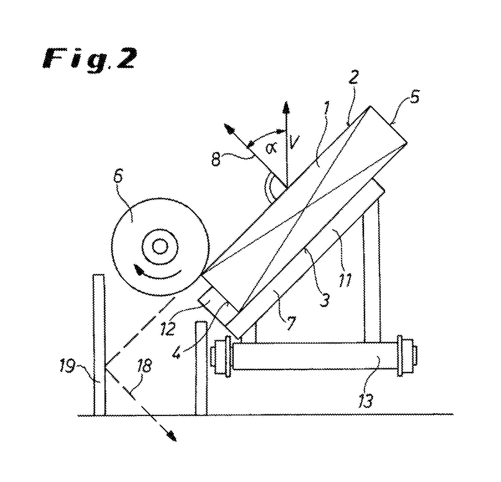
[0021]The invention is based on the discovery that the moment of inertia of the continuously cast product, in particular the slab, about a horizontal transverse axis and thus the resistance to bending increases when the continuously cast product is placed on its narrow side tilted about a longitudinal axis. By reducing the number of stops necessary for the grinding table, the weight of the grinding table can therefore be advantageously reduced.
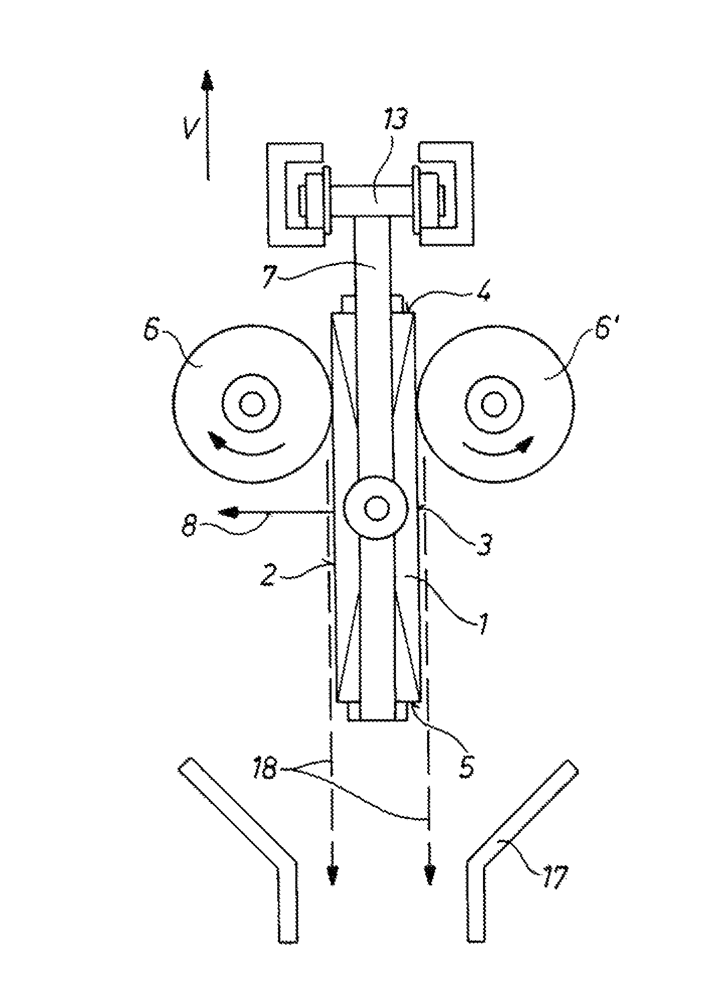
[0022]With the tilted arrangement of the continuously cast product during grinding, furthermore, flying chips are deflected more directly into the chip collection box than in the case of horizontal support, i.e. optimally. The danger of deposits is thus reduced. The chip collection box can therefore be smaller in an is advantageous manner. Thus advantageously flying sparks are oriented in a targeted manner to the floor and a simpler chip collection box can be used.
[0023]In order to reduce the cost for manufacturing the apparatus and in particular for the grinding table and the chip collection box, therefore the object is to increase the moment of inertia of the continuously cast product during the grinding processing, which can be achieved with the cited approach and embodiment respectively according to the invention.
[0026]Another advantage of the proposed solution, in particular with higher slab temperatures, is that the broad sides of the slab can be inspected directly at close range from the side.

Problems solved by technology

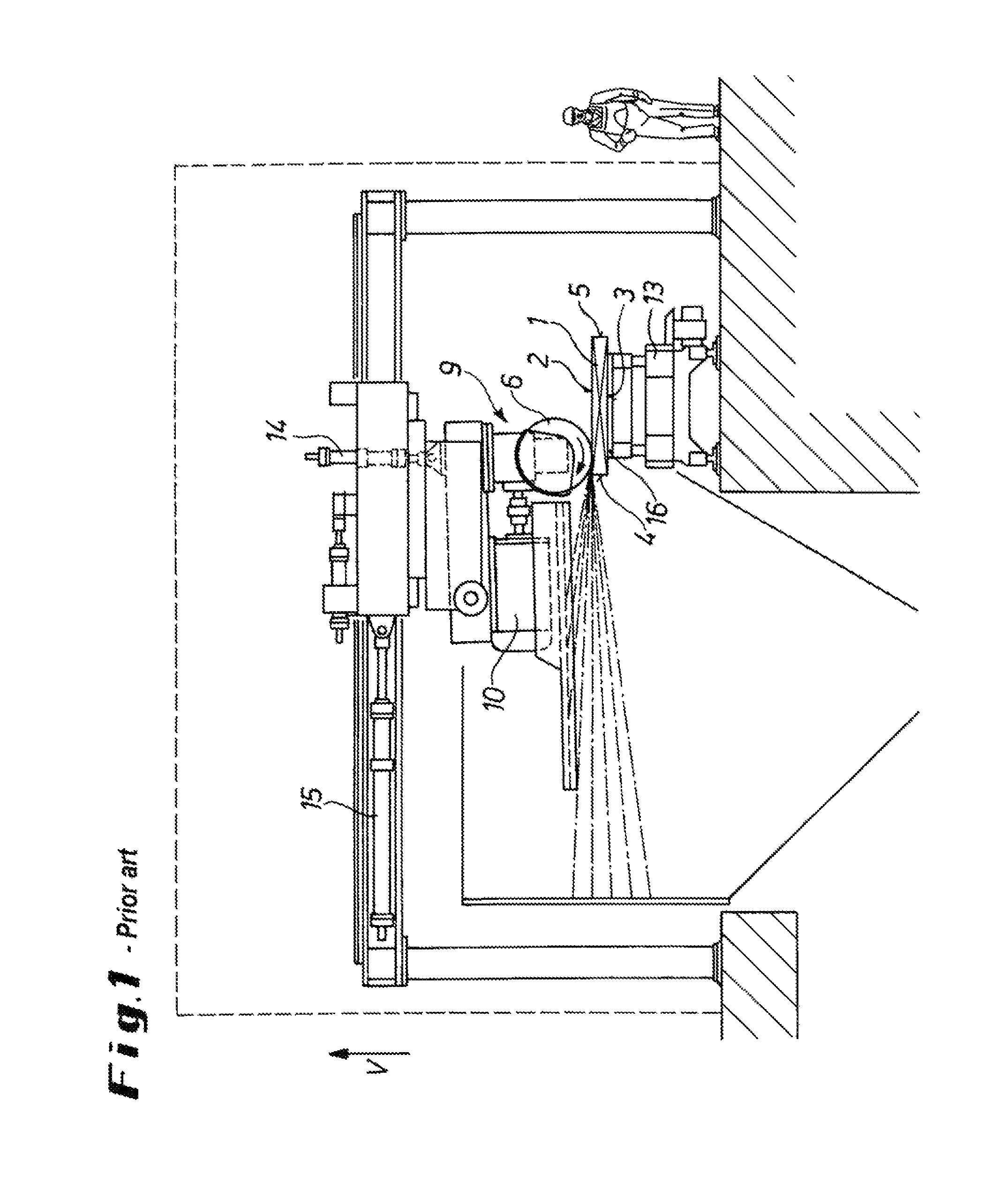
The disadvantage is that, positioned with the broad side on the grinding table 13, the slab 1 has a minimal areal moment of inertia relative to an axis that is horizontal and transverse to the longitudinal axis of the slab.
), there is therefore a danger of bending.
However, this has the negative result of a relatively massive and heavy construction of the grinding table.
This leads in a disadvantageous manner to the slab tending toward undesirable vibrations during grinding with the positioning shown during grinding.
Another problem lies in that considerable deposit of grinding chips on the apparatus can occur when flying chips are not contained optimally during grinding.
Therefore a relatively high maintenance expenditure is necessary with solutions previously known in order to keep the apparatus in optimal use condition.

Method used


Image

  • Method and device for grinding a continuous casting product
  • Method and device for grinding a continuous casting product
  • Method and device for grinding a continuous casting product

Examples


Embodiment Construction

[0034]FIG. 2 diagrammatically illustrates an apparatus for grinding a slab 1 according to the invention. The slab 1 has a rectangular cross section shown in FIG. 2 and extends with its longitudinal axis in a direction perpendicular to the drawing plane. The slab 1 accordingly has two wide side faces 2 and 3 and two narrow edge faces 4 and 5. The wide side faces 2 and 3 are usually at least twice as wide as the narrow edge faces 4, 5, normally much longer.

[0035]The surface of the slab must be processed by grinding in order ultimately to be able to produce a product with sufficient quality from the slab by a subsequent rolling process. To this end, a grinder is provided of which only the grinding wheel 6 is shown in FIG. 2. An arrow indicates the direction of rotation of the grinding wheel 6 during the operation.

[0036]In order to increase the areal moment of inertia about a horizontal axis running transversely to the longitudinal direction of the slab and consequently to minimize bend...


PUM

PropertyMeasurementUnit
temperatureaaaaaaaaaa
temperaturesaaaaaaaaaa
acute angleaaaaaaaaaa

Abstract

A cast slab having a pair of wide, substantially planar, and opposite side faces and a pair of narrow opposite edge faces, is ground by first orienting the slab with the side and edge faces vertical. Then grinding tools are pressed oppositely and horizontally against opposite wide faces, with the grinders throwing the chips downward. The tools and slab are relatively vertically displaced for the grinding.

Description

CROSS REFERENCE TO RELATED APPLICATIONS[0001]This application is the US-national stage of PCT application PCT / EP2010 / 001731, filed 19 Mar. 2010, published 23 Sep. 2010 as WO2010 / 105839, and claiming the priority of German patent application 102009013481.6 itself filed 19 Mar. 2009.FIELD OF THE INVENTION[0002]The invention relates to a method of grinding a continuously cast product, in particular a slab, where the continuously cast product is of rectangular cross section with two wide side faces lying opposite one another and two narrow edge faces lying opposite one another, at least the wide side faces being subjected to a surface treatment by at least one grinding tool. Furthermore, the invention relates to an apparatus for grinding a continuously cast product.BACKGROUND OF THE INVENTION[0003]Continuously cast products, in particular slabs, are subjected to surface treatment by grinding after continuous casting in order to obtain an adequate quality during the further processing of...

Claims


Application Information

Patent Timeline
Patent Type & Authority Patents(United States)
IPC IPC(8): B22D11/12B24B7/00B24B27/04
CPCB24B7/005B22D11/12B24B27/04B21B45/04
Inventor HOFMANN, KARL ROBERTSCHILLER, GUENTERLEUKEL, ANDREAS
Owner SMS LOGISTIKSYST
Learn More