
Controlled transport system for an elliptic charged-particle beam

a technology of charged particles and controlled transport, applied in the direction of discharge tubes/lamp details, magnetic discharge control, instruments, etc., can solve the problems of numerical cumbersomeness, degradation of beam brightness, and inability to achieve global-optimal solutions

Inactive Publication Date: 2011-05-26
MASSACHUSETTS INST OF TECH
View PDF36 Cites 4 Cited by
  • Summary
  • Abstract
  • Description
  • Claims
  • Application Information

AI Technical Summary

Benefits of technology

[0008]According to one aspect of the invention, there is provided a charged-particle beam control system. The charged-particle beam control system includes a plurality of external magnets that generate an axially-varying longitudinal magnetic (AVLM)/axially-varying quadrupole magnetic (AVQM) field. A plurality of external electrode geometries generates an axially-varying longitudinal electrostatic (AVLE)/axially-varying quadrupole electrostatic (AVQE) field. The external electrode geometries and magnets control and confine a charged-particle beam of elliptic cross-section. A depressed collector collects the charged-particle beam. The depressed collector includes one or more electrodes, and a collection surface onto which a beam impacts. The electrodes and collection surface create an electric field that enforces a flow profile in the beam that is substantially similar to a reversed Child-Langmuir flow.
[0009]According to another aspect o

Problems solved by technology

High-intensity, large aspect-ratio elliptic beams are of great interest because of their applications in particle accelerators and vacuum electron devices, but their inherent three-dimensional (3D) nature presents significant theoretical, design, and experimental challenges in the development of elliptic beam systems.
For a 3D system, such as an elliptic charged-particle beam, the traditional approach is numerically cumbersome and will not obtain a globally-optimum solution.
As a result, beam systems designed using these approaches will result in a degradation of beam brightness, increased noise, particle loss, and reduced efficiency.
This compensation, however, creates beam density nonuniformity and contributes to a degradation of beam brightness.
If the proper focusing field structure is not applied, the beam can undergo envelope oscillations which contribute to beam brightness degradation and particle loss.

Method used


Image

  • Controlled transport system for an elliptic charged-particle beam
  • Controlled transport system for an elliptic charged-particle beam
  • Controlled transport system for an elliptic charged-particle beam

Examples


Embodiment Construction

[0027]The invention includes a controlled transport system and a compact, high-efficiency depressed collector for an elliptic charged-particle beam system.

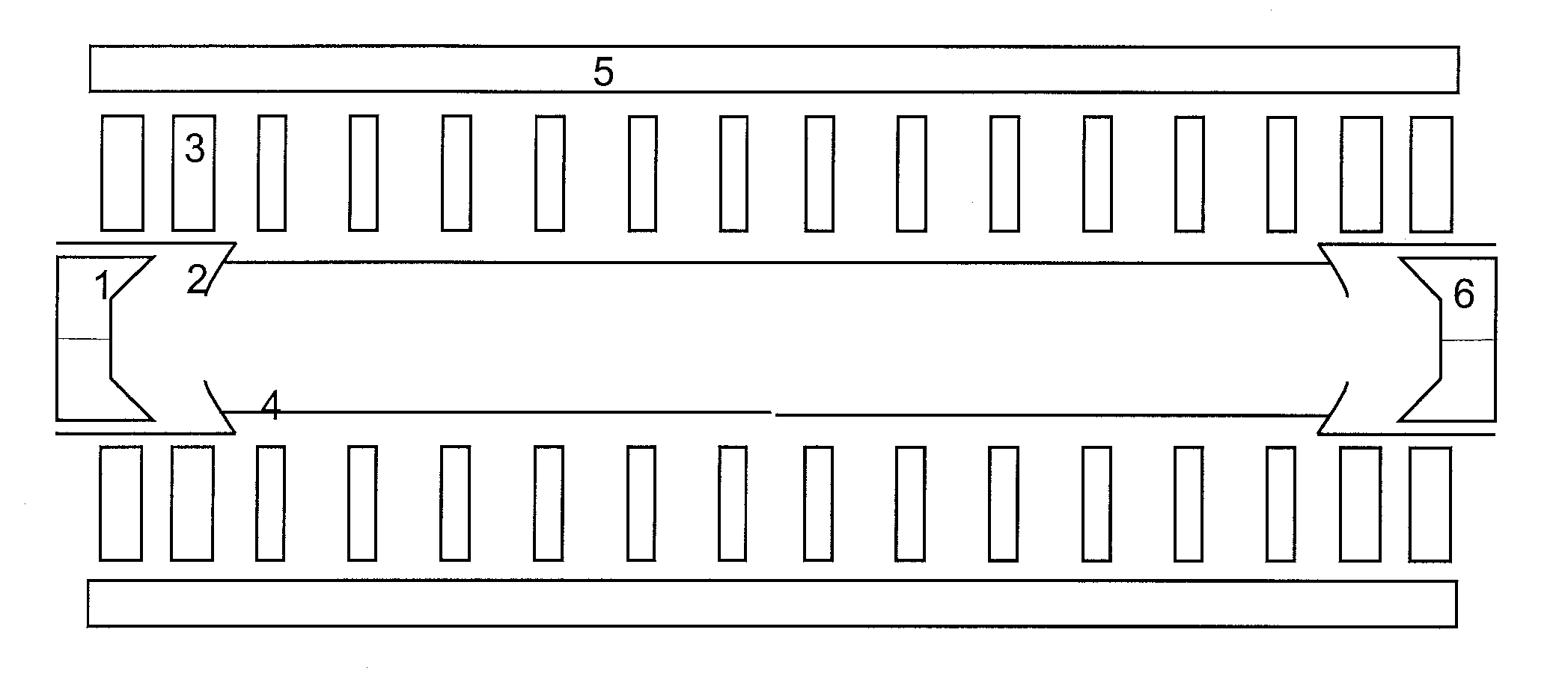
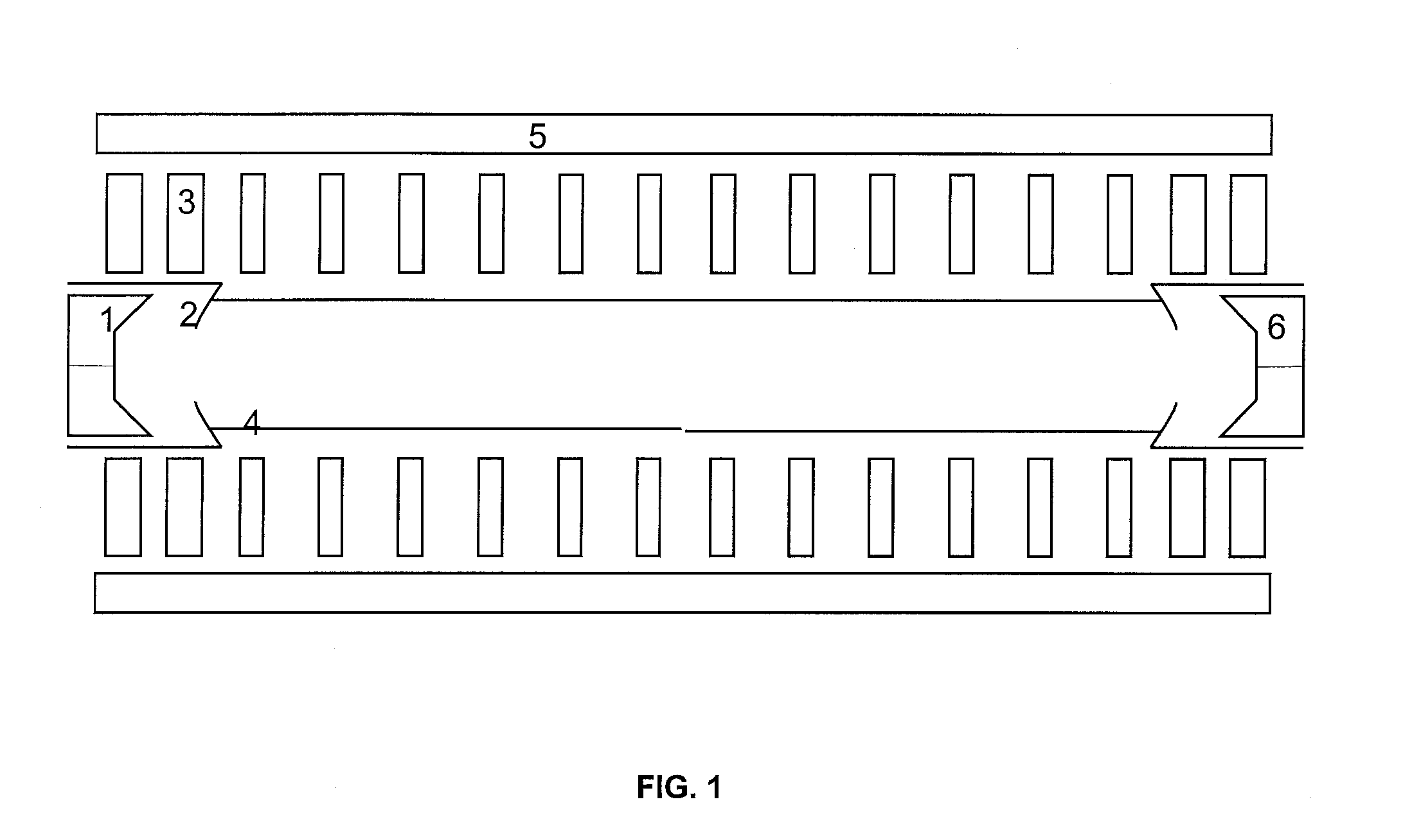
[0028]FIG. 1 shows a controlled transport system for an elliptic beam used in accordance with the invention, having a charged-particle emitter 1, an electrode geometry 2 that generates an axially-varying longitudinal magnetic (AVLM) field / an axially-varying quadrupole electrostatic (AVQE) field that accelerates and focuses the beam, a beam tunnel 4, magnets 3 arranged to produce an AVLM field, magnets 5 arranged to produce an axially-varying quadrupole magnetic (AVQM) field, and a depressed collector with electrode geometry 6 that generates an axially-varying longitudinal electrostatic (AVLE) field / AVQE field that decelerates and focuses the beam.

[0029]The controlled transport system confines an accelerating elliptic beam of uniform density, and the characteristics of the controlled transport system are obtained by solving a matri...


PUM


Abstract

A charged-particle beam control system includes a plurality of external magnets that generate an axially-varying longitudinal magnetic (AVLM) / axially-varying quadrupole magnetic (AVQM) field. A plurality of external electrode geometries generates an axially-varying longitudinal electrostatic (AVLE) / axially-varying quadrupole electrostatic (AVQE) field. The external electrode geometries and magnets control and confine a charged-particle beam of elliptic cross-section.

Description

PRIORITY INFORMATION[0001]This application claims priority from provisional application Ser. No. 60 / 852,037 filed Oct. 16, 2006, which is incorporated herein by reference in its entirety.BACKGROUND OF THE INVENTION[0002]The invention relates to the field of charged-particle beam systems, and in particular to an elliptic charged-particle beam system with an end-to-end controlled beam profile.[0003]High-intensity, large aspect-ratio elliptic beams are of great interest because of their applications in particle accelerators and vacuum electron devices, but their inherent three-dimensional (3D) nature presents significant theoretical, design, and experimental challenges in the development of elliptic beam systems. The traditional approach to charged-particle dynamics problems involves extensive numerical optimization over the space of initial and boundary conditions in order to obtain desired charged-particle trajectories. For a 3D system, such as an elliptic charged-particle beam, the ...

Claims


Application Information

Patent Timeline
IPC IPC(8): H01J1/50
CPCH01J23/02H01J23/087H01J23/083H01J23/08
Inventor BHATT, RONAK J.CHEN, CHIPINGZHOU, JING
Owner MASSACHUSETTS INST OF TECH
Learn More