Lower Structure of Vehicle Body Rear Part

a technology for rear parts and vehicle bodies, which is applied in the direction of roofs, transportation and packaging, vehicle arrangements, etc., can solve the problems of increased vehicle body size, insufficient security deformation of spare tire housings, so as to enhance the rigidity of the rear part of the reinforcing member, and improve the rigidity of the frame front part

Active Publication Date: 2011-05-26
SUZUKI MOTOR CORP
View PDF3 Cites 15 Cited by
  • Summary
  • Abstract
  • Description
  • Claims
  • Application Information

AI Technical Summary

Benefits of technology

[0021]Therefore, according to the lower structure of the vehicle body rear part of the present invention, the rear portion of a spare tire placed so as to tilt forward jumps up with the front portion thereof being the center, so that the turn of the spare tire in the longitudinal direction toward the vehicle front can be promoted, and also the load applied from the vehicle rear can be absorbed reliably.
[0022]In the present invention, the rigidity of the frame front part is enhanced by attaching a spring plate reinforcing member, and the rigidity of the reinforcing member rear part is enhanced by making the closed cross sectional area on the lower side larger than that on the upper side and by attaching the traction hook. Therefore, the above-described effect can be achieved more reliably. A method may also be used in which the plate thickness, the cross section, or the like of the frame front part is increased in place of the attachment of the spring plate reinforcing member to improve the rigidity of the frame front part.
[0023]Also, in the present invention, the rear floor is provided with a bead extending in the vehicle width direction; and the position of the bead, the division position of the frame front part and the frame rear part, and the division position of the reinforcing member front part and the reinforcing member rear part coincide with each other. Therefore, when the rear floor and the hook reinforcing member are bent in a valley form with the division position of the reinforcing member front part and the reinforcing member rear part being a base point, the rear floor is easily bent in a valley form by the bead, so that the valley-form bend occurs in the vehicle width direction reliably. As a result, the deformation load from the rear floor to a spare tire bracket is transmitted efficiently, so that the rear end portion of spare tire can jump up sufficiently.
[0024]Furthermore, in the present invention, the closed cross sectional area of the reinforcing member rear part increases toward the vehicle rear, and a substantially horizontal plane part formed in a maximum closed cross sectional area portion of the reinforcing member rear part is mounted with the traction hook. Therefore, the valley-form bend of the rear floor and the hook reinforcing member, which occurs with the load applied from the vehicle rear, can be caused to occur more reliably and rapidly. Also, the attachment rigidity of the traction hook can be secured, and also the rigidity of the reinforcing member rear part can be reinforced by the traction hook. As a result, the above-described effect can be achieved more reliably, the valley-form bend can be caused to occur smoothly, and the rear end portion of the spare tire can jump up reliably.

Problems solved by technology

In particular, since a fuel tank is disposed in front of the spare tire housing, the deformed spare tire housing may unfavorably contact with the fuel tank.
On the other hand, a space for arranging parts other than the spare tire housing and fuel tank must also be secured, and many restrictions are placed on the layout of vehicle body parts.
Therefore, the space in the rear of the spare tire housing, the distance between the spare tire housing and the fuel tank, and the like cannot be secured sufficiently in many cases.
Also, if an attempt is made to sufficiently secure the space in the rear of the spare tire housing, the distance between the spare tire housing and the fuel tank, and the like, there arises a problem of increased size of vehicle body, which poses a serious problem especially in the case of a compact car.
In this case, there arises a problem that the spare tire contacts with the rear seat.
Also, in the case of the structure such that the hook reinforcing member extending in the vehicle longitudinal direction is provided on the lower surface of the spare tire housing as in JP 2006-88740 A, there arises a problem that the deformation and movement of the spare tire housing cannot be restrained sufficiently.
Furthermore, in the case of the structure such that the spare tire is housed in the spare tire housing in the state in which the rear side of spare tire is raised and the front side of spare tire is tilted downward as in JP 2009-179181 A, there arises a problem that if the tilt is increased for sufficient turning in the longitudinal direction, the vertical dimension of a luggage space decreases, and also there arises a problem that it is difficult to promote the jumping-up of the rear part of the spare tire.

Method used


Image

  • Lower Structure of Vehicle Body Rear Part
  • Lower Structure of Vehicle Body Rear Part
  • Lower Structure of Vehicle Body Rear Part

Examples


Embodiment Construction

[0031]The present invention will now be described in detail based on an embodiment shown in the accompanying drawings.

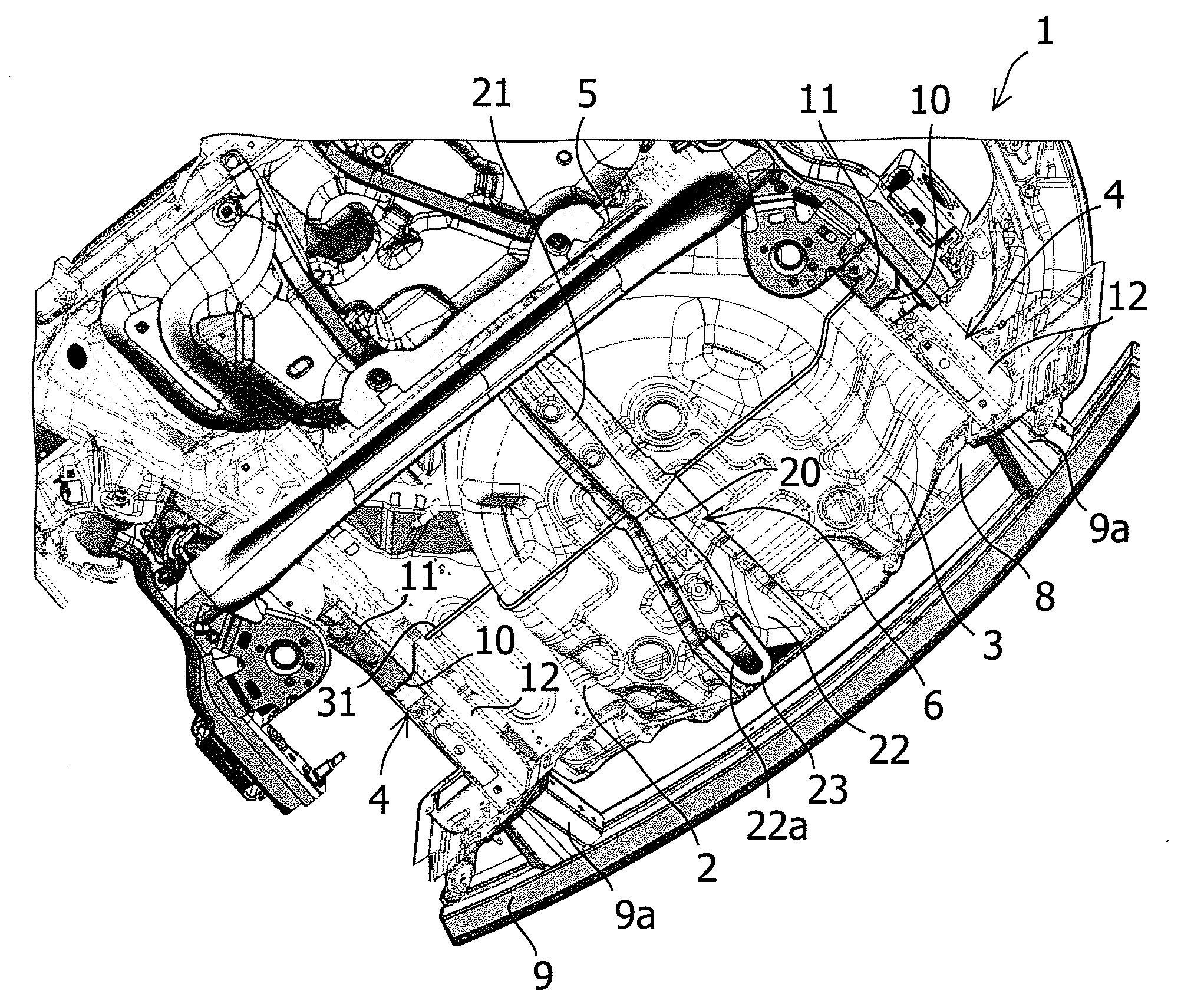
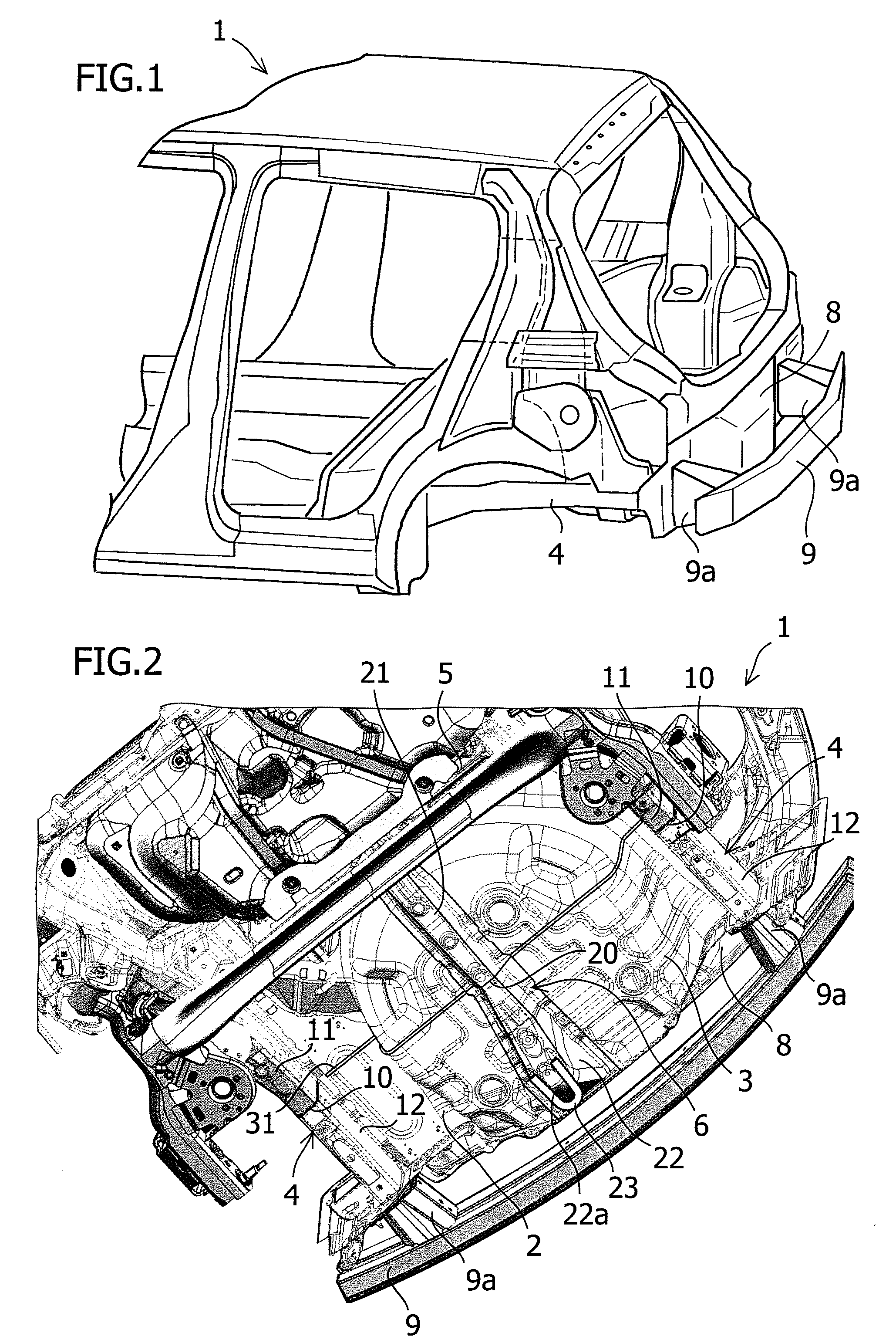
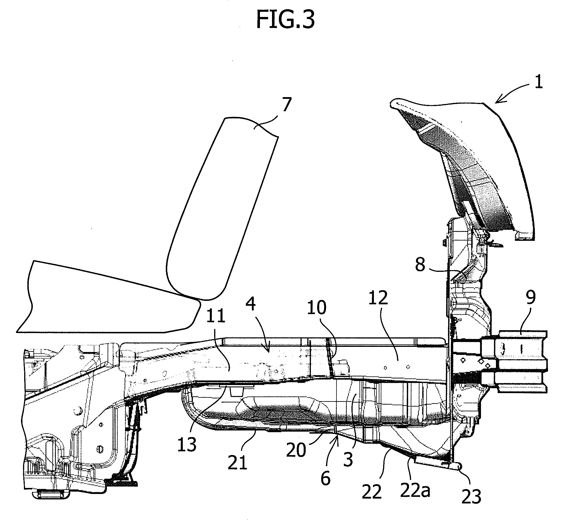
[0032]FIGS. 1 to 6 show a lower structure of a vehicle body rear part in accordance with the embodiment of the present invention.

[0033]As shown in FIGS. 1 to 5, in a lower portion of a vehicle body rear part 1 of a vehicle in accordance with the embodiment of the present invention, a rear floor 2 is provided, and in a central portion of the rear floor 2, a spare tire housing 3, which is a housing concave part for housing a horizontally placed spare tire ST (refer to FIG. 6), is formed. At a position in front of the spare tire housing 3, a rear cross member 5, which connects the right side frame and the left side frame 4 extending along the vehicle longitudinal direction to each other, is disposed, and the rear cross member 5 extends along the vehicle width direction. Also, in the center in the vehicle width direction on the lower surface of the spare tire housing 3, ...


PUM


Abstract

A lower structure of a vehicle body rear part includes a spare tire housing formed on a rear floor, a rear cross member disposed in front of the spare tire housing to connect side frames, and a hook reinforcing member disposed in the center in the vehicle width direction on the lower surface of the spare tire housing and extending in the vehicle longitudinal direction. The front end portion of the hook reinforcing member is connected to the rear cross member, and the rear end portion thereof extends to the rear end portion of the rear floor. The side frame at the vehicle rear of the rear cross member is divided into a frame front part and a frame rear part in the vehicle longitudinal direction, and the hook reinforcing member is divided into a reinforcing member front part and a reinforcing member rear part in the vehicle longitudinal direction. The frame front part has a rigidity higher than that of the frame rear part, and the reinforcing member rear part has a rigidity higher than that of the reinforcing member front part, and the two division positions coincide with each other in the longitudinal direction.

Description

BACKGROUND OF THE INVENTION[0001]1. Field of the Invention[0002]The present invention relates to a lower structure of a vehicle body rear part of a vehicle provided with a spare tire housing formed on a rear floor.[0003]2. Description of Related Art[0004]In a common vehicle, a spare tire housing for housing a spare tire is provided at a rear floor in a vehicle body rear part. For the vehicle having such a structure, when a load is applied from the vehicle rear, the spare tire moves toward the vehicle front, and accordingly the spare tire housing may be deformed and may move to the vehicle front. In particular, since a fuel tank is disposed in front of the spare tire housing, the deformed spare tire housing may unfavorably contact with the fuel tank.[0005]In such a case, countermeasures are conceivable such that the load is absorbed by the surroundings of the spare tire housing by securing a sufficient space between the spare tire housing and a back panel. Also, in the case in which ...

Claims


Application Information

Patent Timeline
Patent Type & Authority Applications(United States)
IPC IPC(8): B62D25/08
CPCB62D43/10B62D21/152
Inventor SOUMA, TAKAYUKINISHIDA, NORIO
Owner SUZUKI MOTOR CORP
Why Eureka
Try Eureka