
Optical touch apparatus and optical touch display apparatus

Inactive Publication Date: 2011-05-26
CORETRONIC
View PDF4 Cites 45 Cited by
  • Summary
  • Abstract
  • Description
  • Claims
  • Application Information

AI Technical Summary

Benefits of technology

[0009]The invention provides an optical touch display apparatus having higher accuracy in determining the touch point.
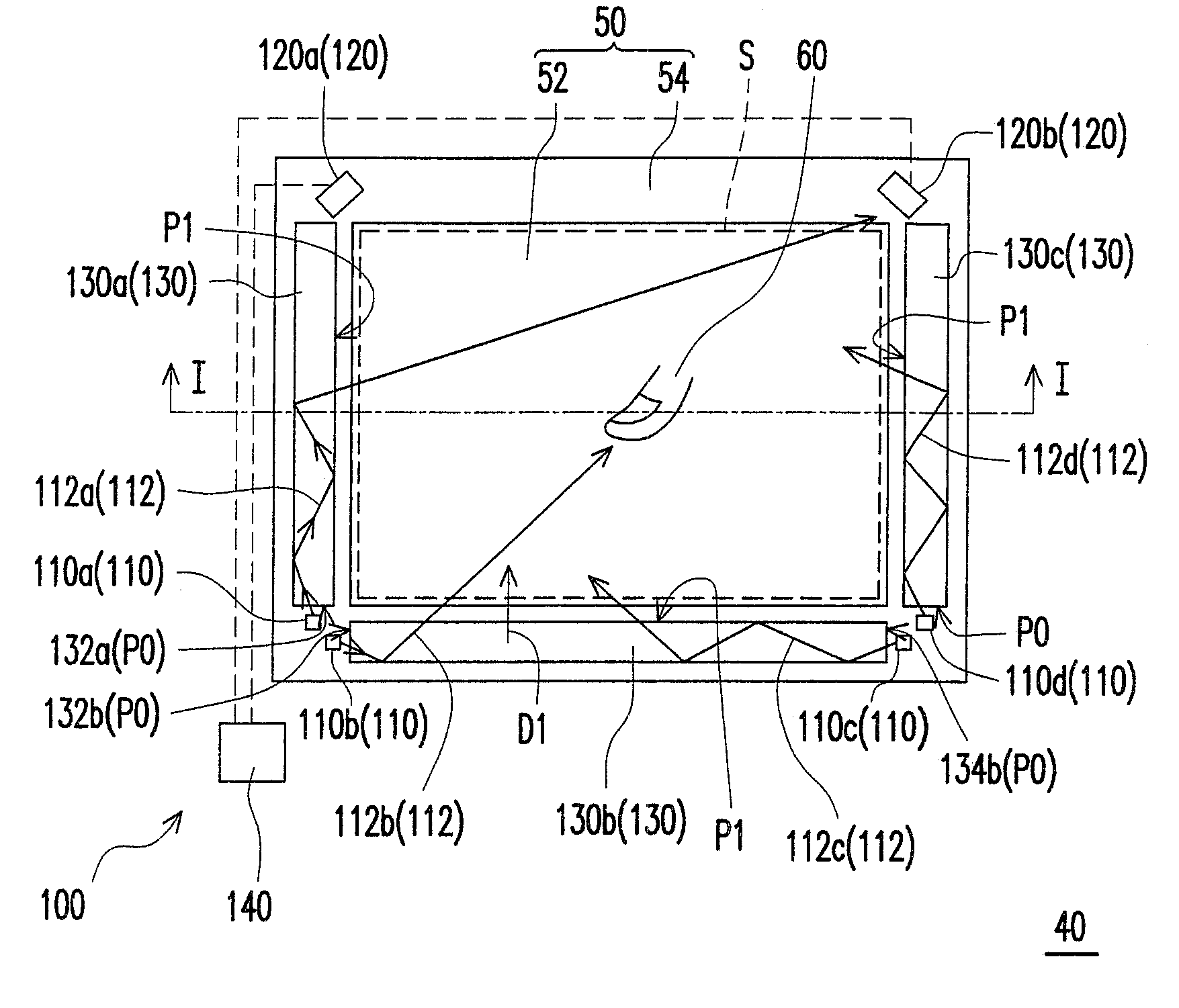
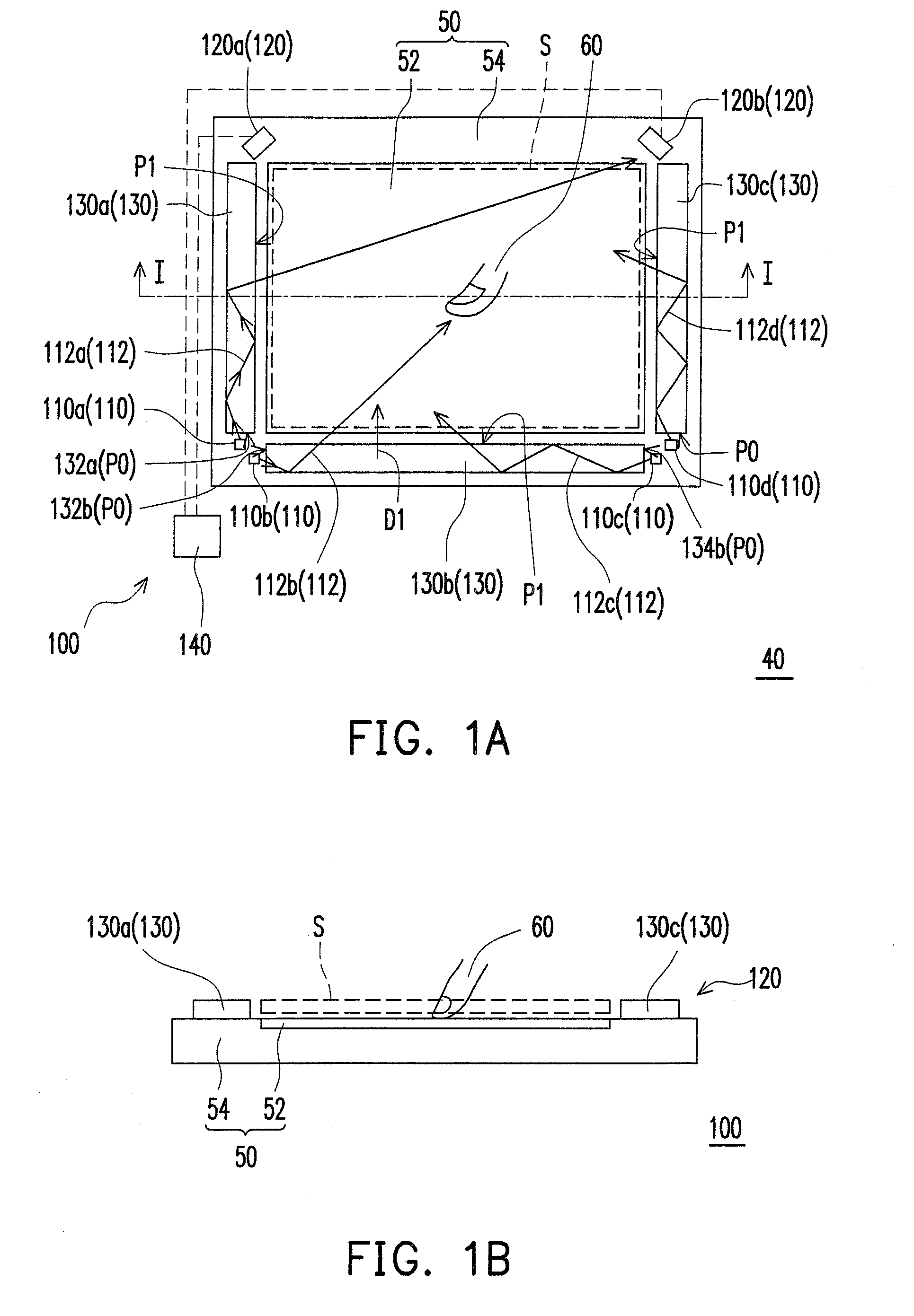
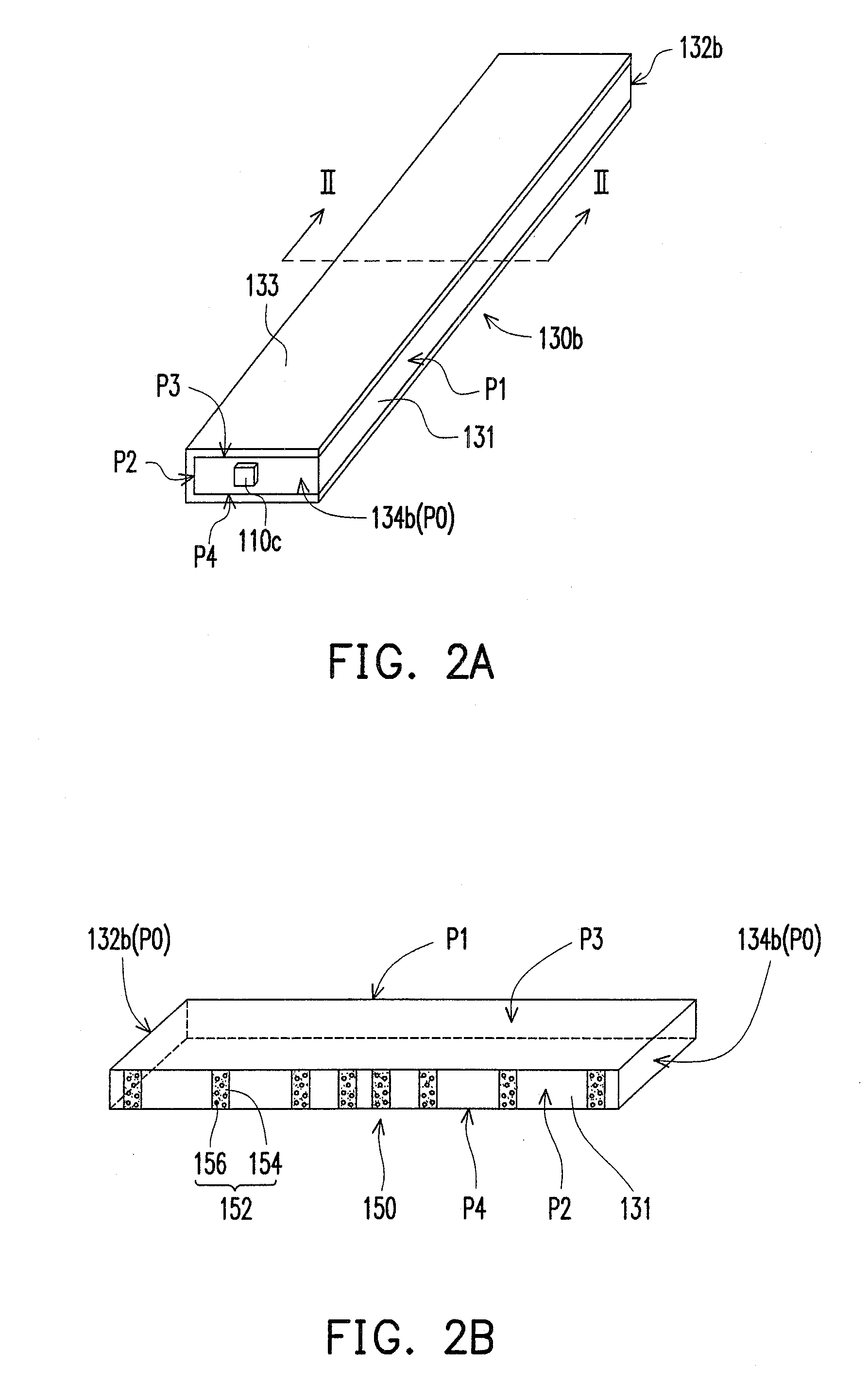
[0013]Due to the above mentions, the embodiments of the invention may have at least one of the following advantages. Since the optical touch apparatus and the optical touch display apparatus of the embodiments of the invention adopt the Lambertian scattering structure, the light shape of the beam emitted from the first surface is similar to a Lambertian intensity distribution, so that the luminance of the first surface detected by the optical detector is more uniform, thereby enhancing the accuracy in determining the position of the touch point by the optical touch apparatus and the optical touch display apparatus.

Problems solved by technology

With the development of optoelectronic technology, a user's requirements may no longer be satisfied by using a mouse to control objects in a computer or on a screen.
However, for ordinary users, the cursor might not be controlled as agilely by the touch pad or the track point next to the keys than by a mouse.
In addition, the uniformity of the luminance of the beam passed through the light guide board affects the accuracy in determining the touch point.
However, according to prior art, the luminance of the beam which has passed through the light guide board is non-uniform, so that the accuracy in determining the position of the touch point is also lower.

Method used


Image

  • Optical touch apparatus and optical touch display apparatus
  • Optical touch apparatus and optical touch display apparatus
  • Optical touch apparatus and optical touch display apparatus

Examples


Embodiment Construction

[0026]In the following detailed description of the preferred embodiments, reference is made to the accompanying drawings which form a part hereof, and in which are shown by way of illustration specific embodiments in which the invention may be practiced. In this regard, directional terminology, such as “top,”“bottom,”“front,”“back,” etc., is used with reference to the orientation of the Figure(s) being described. The components of the present invention can be positioned in a number of different orientations. As such, the directional terminology is used for purposes of illustration and is in no way limiting. On the other hand, the drawings are only schematic and the sizes of components may be exaggerated for clarity. It is to be understood that other embodiments may be utilized and structural changes may be made without departing from the scope of the present invention. Also, it is to be understood that the phraseology and terminology used herein are for the purpose of description an...


PUM


Abstract

An optical touch apparatus includes a light source, light guide unit, and optical detector. The light source next to the display area emits a beam. The light guide unit next to the display area and in the transmission path of the beam includes a light guide body and a Lambertian scattering structure. The light guide body has first, second, third, fourth, and light incident surfaces. The beam enters the light guide body through the light incident surface and is transmitted from the first surface to a sensing space in front of the display area. The Lambertian scattering structure is disposed on at least one of the second, third, and fourth surfaces for scattering the beam to the first surface. The optical detector next to the display area senses a change in light intensity of the beam in the sensing space. An optical touch display apparatus is also provided.

Description

CROSS-REFERENCE TO RELATED APPLICATION[0001]This application claims the priority benefit of Taiwan application serial no. 98140204, filed on Nov. 25, 2009. The entirety of the above-mentioned patent application is hereby incorporated by reference herein and made a part of this specification.BACKGROUND OF THE INVENTION[0002]1. Field of the Invention[0003]The invention is related to a touch apparatus and a display apparatus, and more particularly, to an optical touch apparatus and an optical touch display apparatus.[0004]2. Description of Related Art[0005]With the development of optoelectronic technology, a user's requirements may no longer be satisfied by using a mouse to control objects in a computer or on a screen. Hence, interfaces more user-friendly than the mouse have been gradually developed. In the user-friendly interfaces, the touch method by using fingers is closest to human experiences in daily life. In particular, elders and children who may not use the mouse agilely may t...

Claims


Application Information

Patent Timeline
IPC IPC(8): G06F3/042
CPCG02B6/0028G06F3/0428G02B6/0061G02B6/0043
Inventor TSANG, CHIH-JENLIAO, CHUN-CHIENJHU, YU-LUNLIEN, CHENG-YI
Owner CORETRONIC
Learn More