

Fixing device and image forming apparatus
a fixing device and image forming technology, applied in the field of image forming apparatus, can solve the problems of fixing variation spot of developer on the printing medium, member tends to dissipate heat, etc., and achieve the effect of reducing cold offset generated and reducing the fixing variation spot of developer
- Summary
- Abstract
- Description
- Claims
- Application Information
AI Technical Summary
Benefits of technology
Problems solved by technology
Method used
Image

Examples
first embodiment
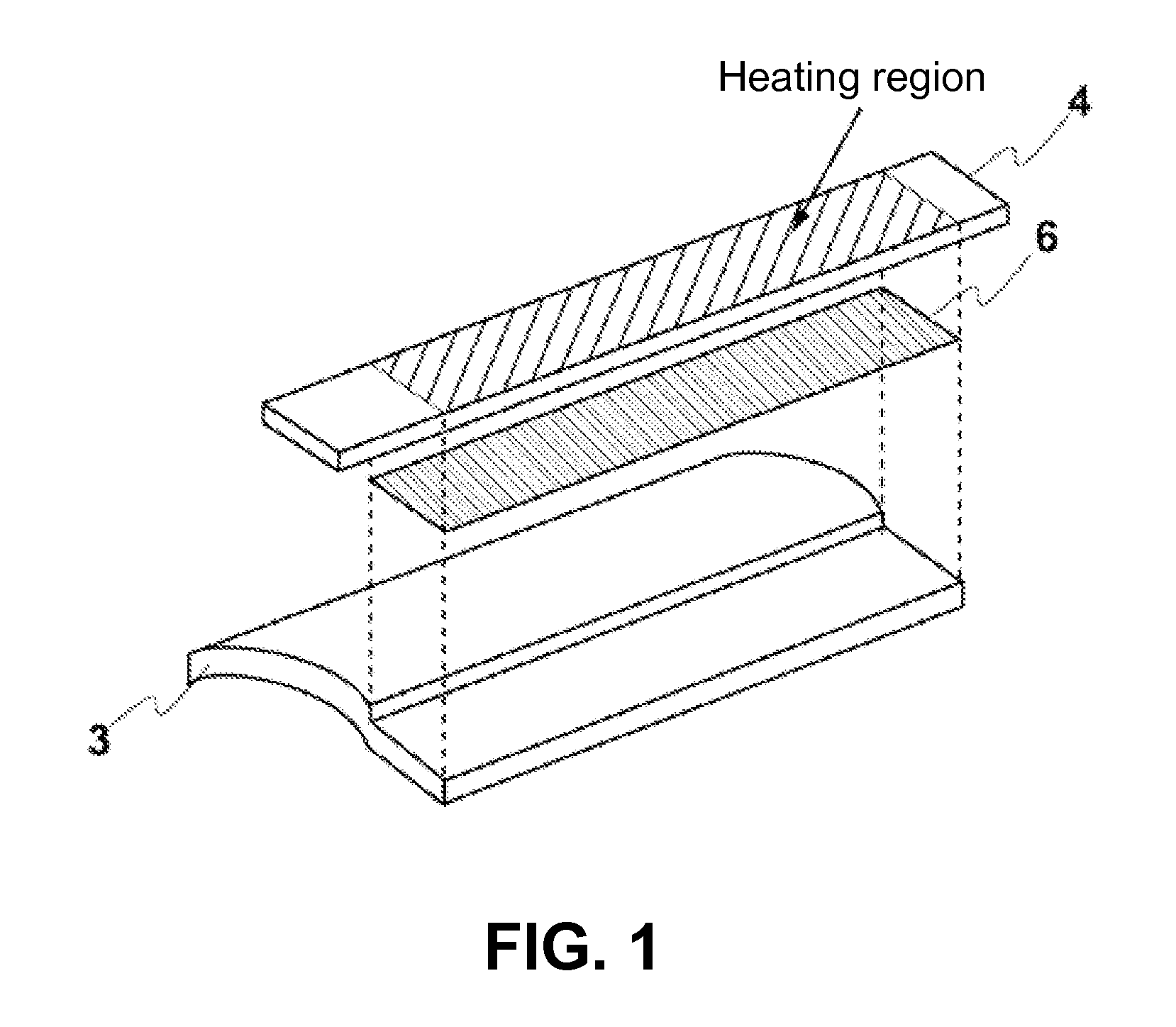
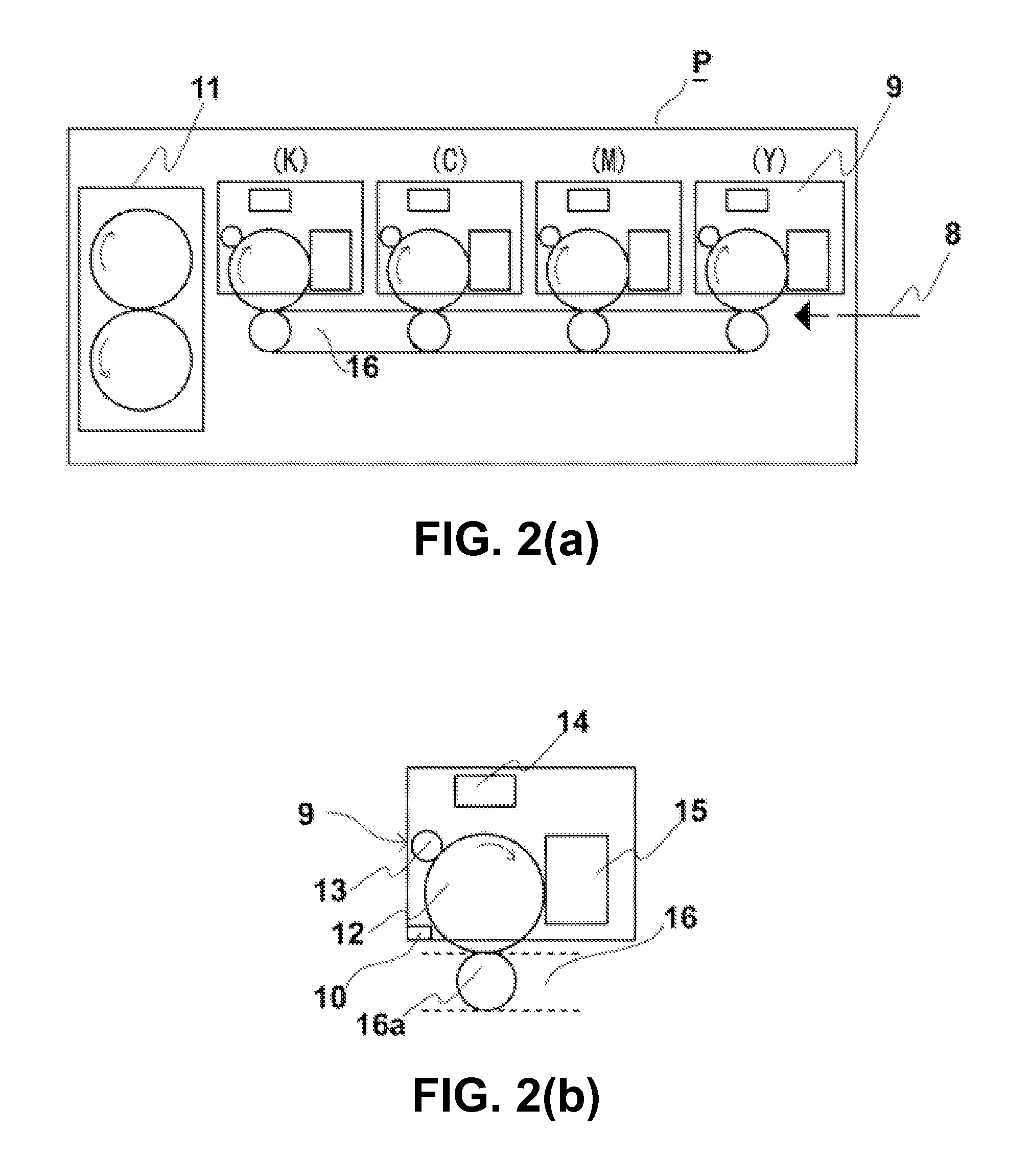
[0029]A first embodiment of the present invention will be explained. FIG. 2(a) is a schematic sectional view showing an entire configuration of the printer P including a fixing device 11 according to the first embodiment of the present invention. FIG. 2(b) is a schematic sectional view showing a partial configuration of the printer P including the fixing device 11 according to the first embodiment of the present invention.
[0030]As shown in FIG. 2(a), the printer P includes image forming units 9 for forming images in black (K), cyan (C), magenta (M), and yellow (Y); a transportation unit 16 having transfer rollers 16a corresponding to the image forming units 9 and a belt in an endless shape disposed below the image forming units 9 for transporting a printing medium 8; and the fixing device 11 having a fixing roller 1 and a pressing roller 5 facing each other for heating and pressing the printing medium 8, so that developer (toner) 7 (refer to FIG. 3) is fixed to the printing medium 8...
second embodiment
[0064]A second embodiment of the present invention will be explained next. In the second embodiment, similar to the first embodiment, the printer will be explained as the image forming apparatus. Components in the second embodiment similar to those in the first embodiment are designated with the same reference numerals.
[0065]As shown in FIG. 3, the fixing device 11 includes the fixing roller 1, the pressing roller 5 disposed to face the fixing roller 1; and the fixing belt 2 extended between the fixing roller 1 and the supporting member 3. In the fixing device 11, when the transportation unit 16 transports the printing medium 8 with the toner 7 still not fixed, the fixing belt 2 and the pressing roller 5 each rotating sandwich the printing medium 8 to heat and press the printing medium 8, so that the toner 7 is fixed to the printing medium 8.
[0066]As shown in FIG. 4(a), the fixing roller 1 includes the metal core 17 in a drum shape fitted to the rotational shaft 1a and the elastic l...
third embodiment
[0094]A third embodiment of the present invention will be explained next. In the third embodiment, similar to the first embodiment, the printer will be explained as the image forming apparatus. Components in the third embodiment similar to those in the first embodiment are designated with the same reference numerals.
[0095]As shown in FIG. 3, the fixing device 11 includes the fixing roller 1, the pressing roller 5 disposed to face the fixing roller 1; and the fixing belt 2 extended between the fixing roller 1 and the supporting member 3. In the fixing device 11, when the transportation unit 16 transports the printing medium 8 with the toner 7 still not fixed, the fixing belt 2 and the pressing roller 5 each rotating sandwich the printing medium 8 to heat and press the printing medium 8, so that the toner 7 is fixed to the printing medium 8.
[0096]As shown in FIG. 4(a), the fixing roller 1 includes the metal core 17 in a drum shape fitted to the rotational shaft 1a and the elastic laye...
PUM
 Abstract
Description
Claims
Application Information