Photobioreactor

a photobioreactor and microorganism technology, applied in bioreactors/fermenters, specific use bioreactors, after-treatment of biomass, etc., can solve the problems of high cost of biomass production, high production cost of phototrophic microorganisms, etc., to reduce the risk of contamination as compared to open systems, the effect of high production cos

Active Publication Date: 2011-05-26
AVESTON GRIFFORD
View PDF6 Cites 29 Cited by
  • Summary
  • Abstract
  • Description
  • Claims
  • Application Information

AI Technical Summary

Benefits of technology

This invention introduces a new device called a photbioreactor that helps produce biofuel from photosynthetic organisms more efficiently at lower costs than current methods. It also reduces the chance of getting sick from harmful bacteria or other living things.

Problems solved by technology

The technical problem addressed in this patent is the high cost and risk of contamination in the production of algae biomass, which makes it difficult to commercialize for many applications. The patent aims to provide a solution by introducing a new device for algae production that is simpler and cheaper than existing bioreactor arrangements.

Method used


Image

  • Photobioreactor
  • Photobioreactor
  • Photobioreactor

Examples


example

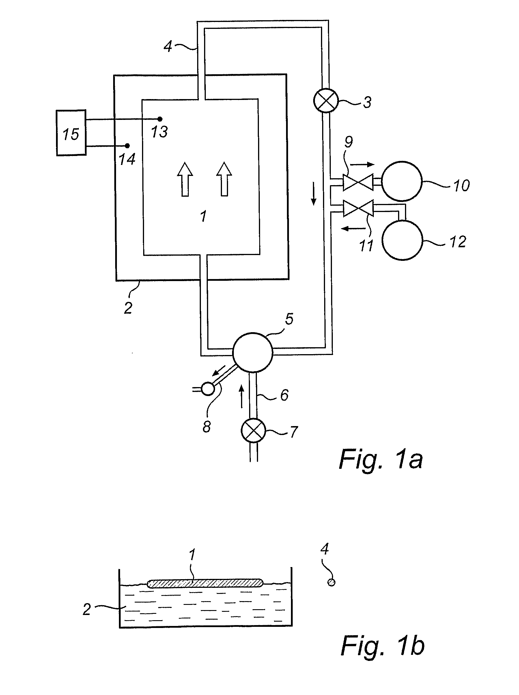
[0131]A flexible closed flat panel photobioreactor made of a flexible polyethylene film and having the dimensions 7 meter×5 meter, was placed on the surface of a basin containing water with a salinity of 35 g / L. The algae compartment of the photobioreactor was fed with 1,800 liters of fresh water colored with methyl blue. The photobioreactor containing the colored solution (representing the culture liquid) arranged itself floating on the surface of the surrounding water, with the culture medium being homogeneously distributed over the bottom surface of the reactor.

[0132]The photobioreactor was lowered into the surrounding water by feeding water saturated with salt into an additional compartment positioned on the top side of the algae compartment. The salt water was pumped in from one side of the additional compartment only, via five liquid ports equally distributed along the longer side of the additional compartment. The reactor system started to sink at the side where the heavier s...


PUM


Abstract

A method of operating a closed photobioreactor for cultivation of phototrophic microorganisms. The photobioreactor comprises a culture liquid and is partially or completely surrounded by water of a water body. A density difference between the culture liquid and the surrounding water is provided so that the position of the photobioreactor in the water body is controlled. A closed photobioreactor for cultivation of phototrophic microorganisms. The photobioreactor is adapted to comprise a culture liquid and to be partially or completely surrounded by water of a water body. The photobioreactor comprises means for determining the density difference between the culture liquid and the surrounding water.

Description


Claims


Application Information

Patent Timeline
Owner AVESTON GRIFFORD
Why Eureka
Try Eureka