
Thermostimulation system including multilayer pads with integrated temperature regulations

a multi-layer, temperature regulation technology, applied in the field of therapeutic systems, can solve the problems of limiting performance and patient benefit, a small amount of power applied, and low treatment depth of the resulting electric field

Inactive Publication Date: 2011-05-26
LOUISE MOHN
View PDF25 Cites 13 Cited by
  • Summary
  • Abstract
  • Description
  • Claims
  • Application Information

AI Technical Summary

Benefits of technology

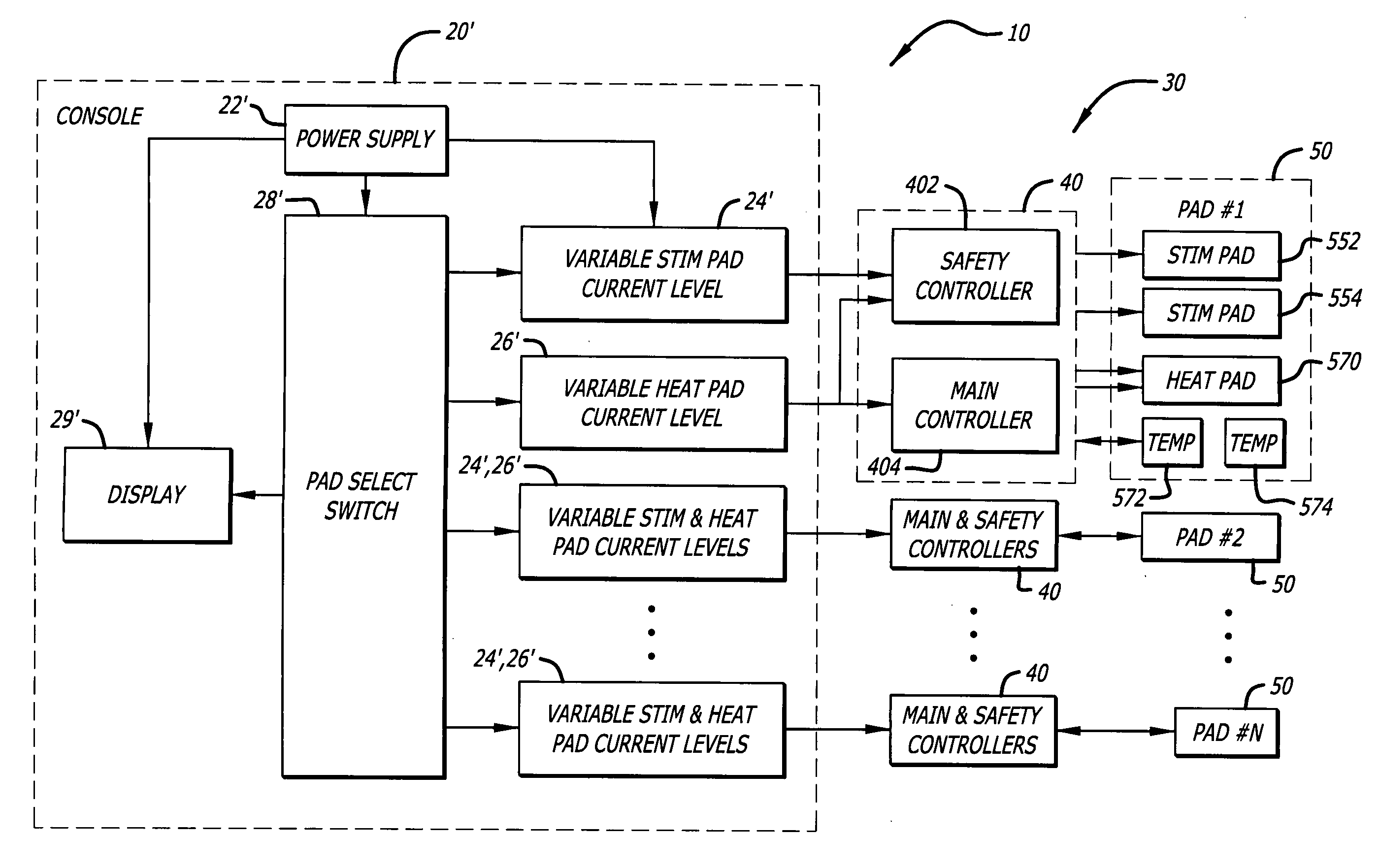
[0012]In more specific embodiments, plural pads and inline control systems are connected to the console. Each inline control system has a first microprocessor for providing heat and stimulation current control for the pad and a second microprocessor for providing over-temperature control for the pad. Each inline control system has a display and a button to allow confirmation of temperatures of more than 38 degrees Celsius. Each pad has a connector integrated multilayer construction with a heating element implemented with a wire matrix and slots for flexibility. In addition to a temperature sensor, each pad also includes two electrical stimulation contacts having a wire conductor along the length thereof. Each pad is connected to an associated inline control system via a flat cable. Specially designed strain relief grommets are provided on both ends of the flat cable where they terminate with the pad or inline control system.

Problems solved by technology

This results in the application of a small amount of power and a low treatment depth of the resulting electric field.
The shallow depth of the electric field generated by conventional electrical stimulation systems limits performance and patient benefit.
However, the small size of conventional electrical stimulation pads is such that on the application of larger amounts of power, i.e. the use of higher currents, patients often report the experience of pain or discomfort.
Unfortunately, there are several problems associated with conventional thermostimulation systems.
One problem is due to poor or inadequate pad design.
In addition, conventional pads tend to exhibit a current fall off over the length of the pad.
This limits the performance of conventional pads.
Further, the connectors are subject to detachment and therefor often fail to comply with government requirements in certain countries.
Further, conventional thermostimulation pads are not waterproof.
As a consequence, sweat from the patient combined with the pad gel can cause the stimulation connector and press studs to short directly to the patient, which can result in the patient being shocked or burned.
Moreover, conventional thermostimulation pads are generally inflexible and yield to breakage of the heating element if bent or folded too frequently.
More significantly, conventional thermostimulation pads are not designed to detect, measure and / or monitor temperature of the pad when on the patient.
Consequently, effective temperature regulation is not provided with conventional thermostimulation systems.

Method used


Image

  • Thermostimulation system including multilayer pads with integrated temperature regulations
  • Thermostimulation system including multilayer pads with integrated temperature regulations
  • Thermostimulation system including multilayer pads with integrated temperature regulations

Examples


Embodiment Construction

[0036]Illustrative embodiments and exemplary applications will now be described with reference to the accompanying drawings to disclose the advantageous teachings of the present invention.

[0037]While the present invention is described herein with reference to illustrative embodiments for particular applications, it should be understood that the invention is not limited thereto. Those having ordinary skill in the art and access to the teachings provided herein will recognize additional modifications, applications, and embodiments within the scope thereof and additional fields in which the present invention would be of significant utility.

Conventional Thermostimulation System

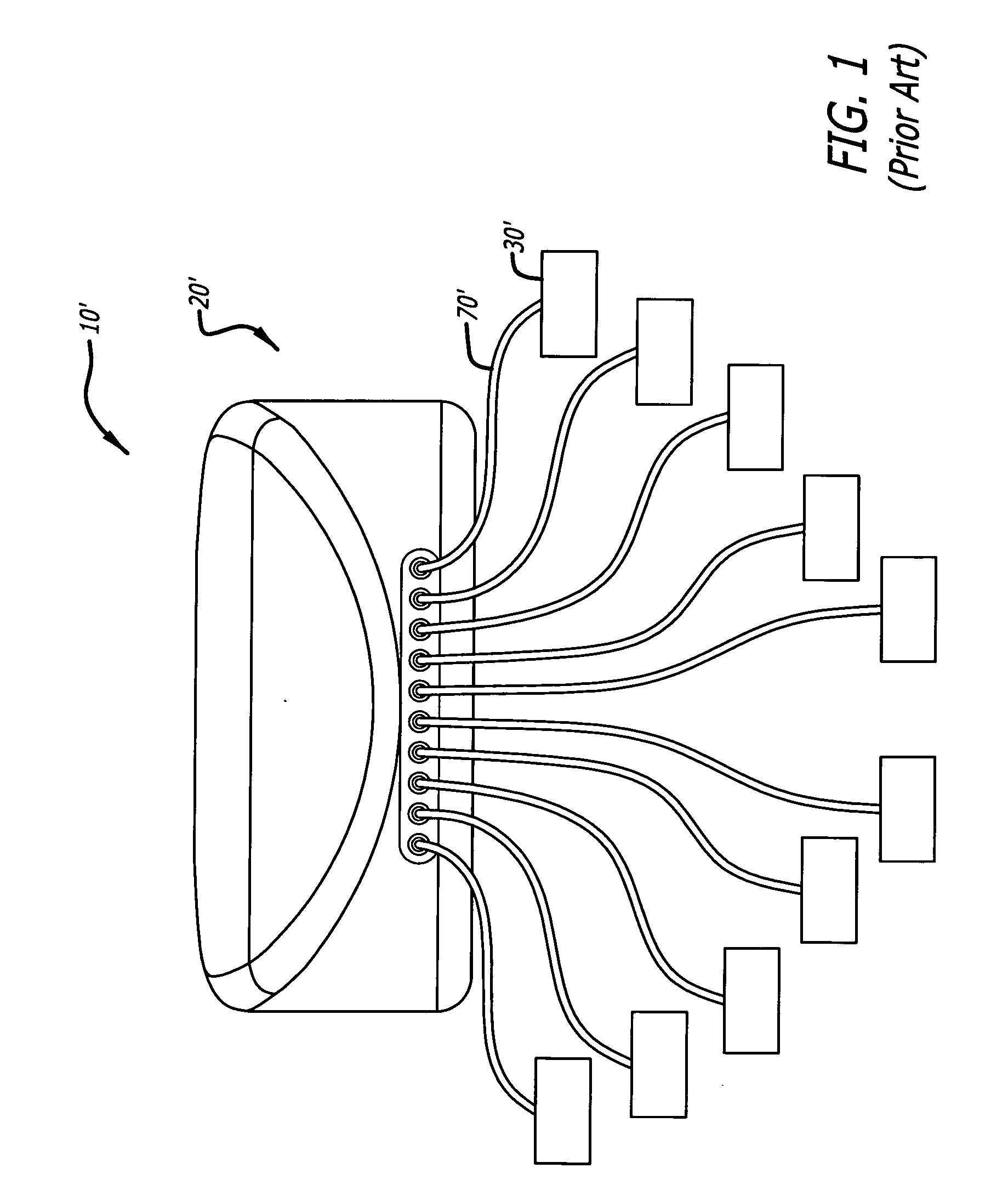
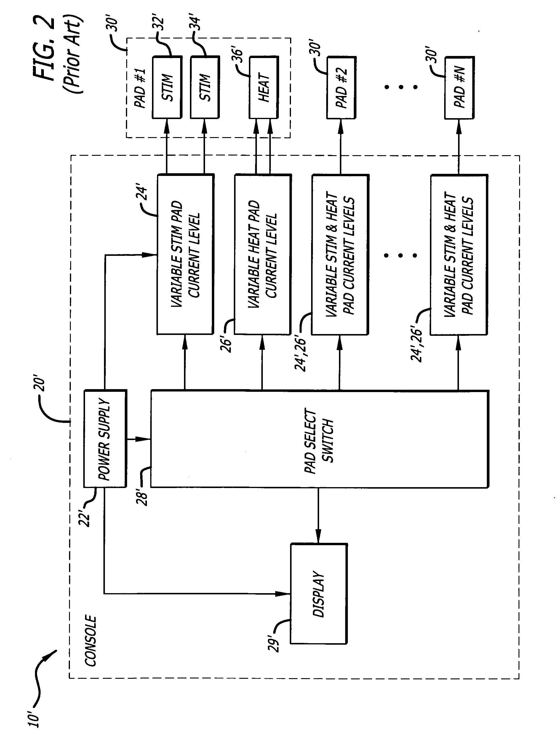
[0038]FIG. 1 is a perspective view of a typical thermostimulation system implemented in accordance with conventional teachings. The system 10′ includes a conventional thermostimulation console 20′ and a plurality of thermostimulation pads 30′. The console may be purchased from Ross Estetica of Barcelona Spain. (Se...


PUM


Abstract

A thermostimulation system and method. The inventive thermostimulation system is adapted for use with a console for providing electrical currents for thermal and electrical stimulation in response to a first input from an operator via at least one electrical connector. Generally, the inventive thermostimulation system includes at least one inline control system coupled to the console via electrical connector for regulating the currents to an associated thermostimulation pad via a second connector. The pad has a temperature sensor adapted to provide a feedback signal to the inline control system. In more specific embodiments, plural pads and inline control systems are connected to the console. Each inline control system has a first microprocessor for providing heat and stimulation current control for the pad and a second microprocessor for providing overcurrent safety control for the pad. Each inline control system has a display and a patient over-temperature control switch. Each pad has a connector integrated multilayer construction with a heating element implemented with a wire matrix and slots for flexibility. In addition to a temperature sensor, each pad also includes two electrical stimulation contacts having a wire conductor along the length thereof. Each pad is connected to an associated inline control system via a flat connector. Specially designed strain relief grommets are provided on both ends of the flat cable.

Description

BACKGROUND OF THE INVENTION[0001]1. Field of the Invention[0002]The present invention relates to therapeutic systems. More specifically, the present invention relates to methods and apparatus for providing electrical and thermal stimulation.[0003]2. Description of the Related Art[0004]For a variety of therapeutic applications, several treatment modalities are currently known in the art including electrical stimulation, heat therapy and thermostimulation. Electrical stimulation involves the application of an electrical current to a single muscle or a group of muscles. The resulting contraction can produce a variety of effects from strengthening injured muscles and reducing oedema to relieving pain and promoting healing. Many electrical stimulation systems are limited to two to four channels and therefore allow only two to four pads to be applied to a patient. The pads are usually quite small and typically powered with a battery. This results in the application of a small amount of po...

Claims


Application Information

Patent Timeline
Patent Type & Authority Applications(United States)
IPC IPC(8): A61F7/00A61N1/36
CPCA61F7/007A61F2007/0071A61F2007/0096A61N1/36014A61N1/048A61N1/0496A61N1/36003A61N1/0452A61N1/3603A61N1/36034
Inventor LOUISE, MOHN
Owner LOUISE MOHN
Learn More