Self-Expanding Stent with Polygon Transition Zone

a transition zone and self-expanding technology, which is applied in the field of self-expanding stents with polygon transition zones, can solve the problems of change in stress or bending moment of stents across the transition zone, collapse of balloon expandable stents,

Active Publication Date:
View PDF48 Cites 63 Cited by
  • Summary
  • Abstract
  • Description
  • Claims
  • Application Information

AI Technical Summary

Benefits of technology

[0017]In one embodiment, the loops may further comprise a hole positioned in the loop. Adjacent holes may have unequal surface areas. The surface area of the hole may increase in a clockwise or counterclockwise manner relative to the long axis of the stent.

Problems solved by technology

Balloon expandable stents may suffer from the collapse as a result of the natural elastic recoil of the vessel wall and lack of resilience of the stent itself.
Each of the various stent designs that have been used with self-expanding stents has certain functional problems.
Such a variation can result in a change in stress or bending moment of the stent across the transition zone.
This lack of uniformity affects the ability of the stent to be uniformly compressed and expanded which in turn impacts insertion of the stent into a convoluted vessel.

Method used


Image

  • Self-Expanding Stent with Polygon Transition Zone
  • Self-Expanding Stent with Polygon Transition Zone
  • Self-Expanding Stent with Polygon Transition Zone

Examples


Embodiment Construction

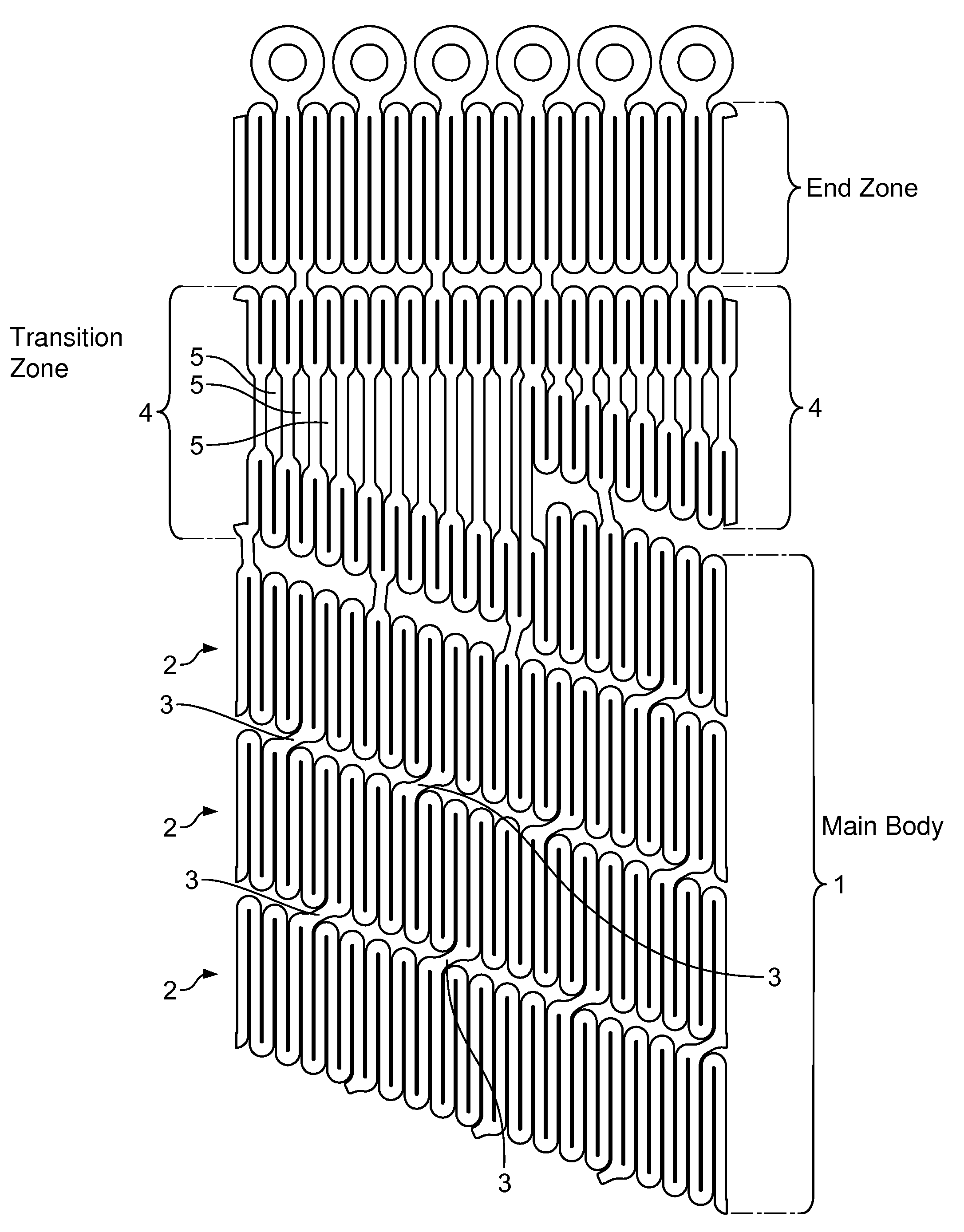
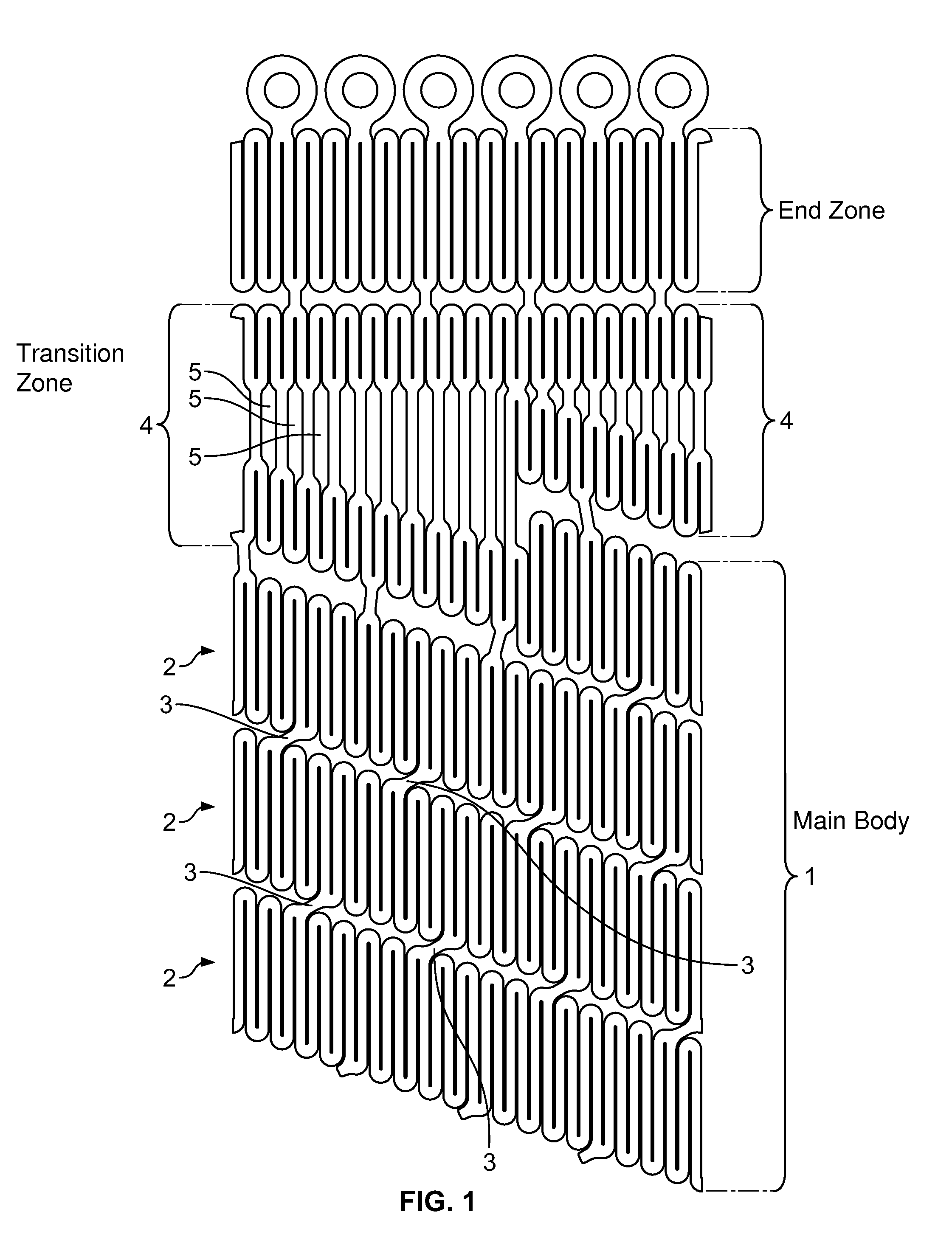
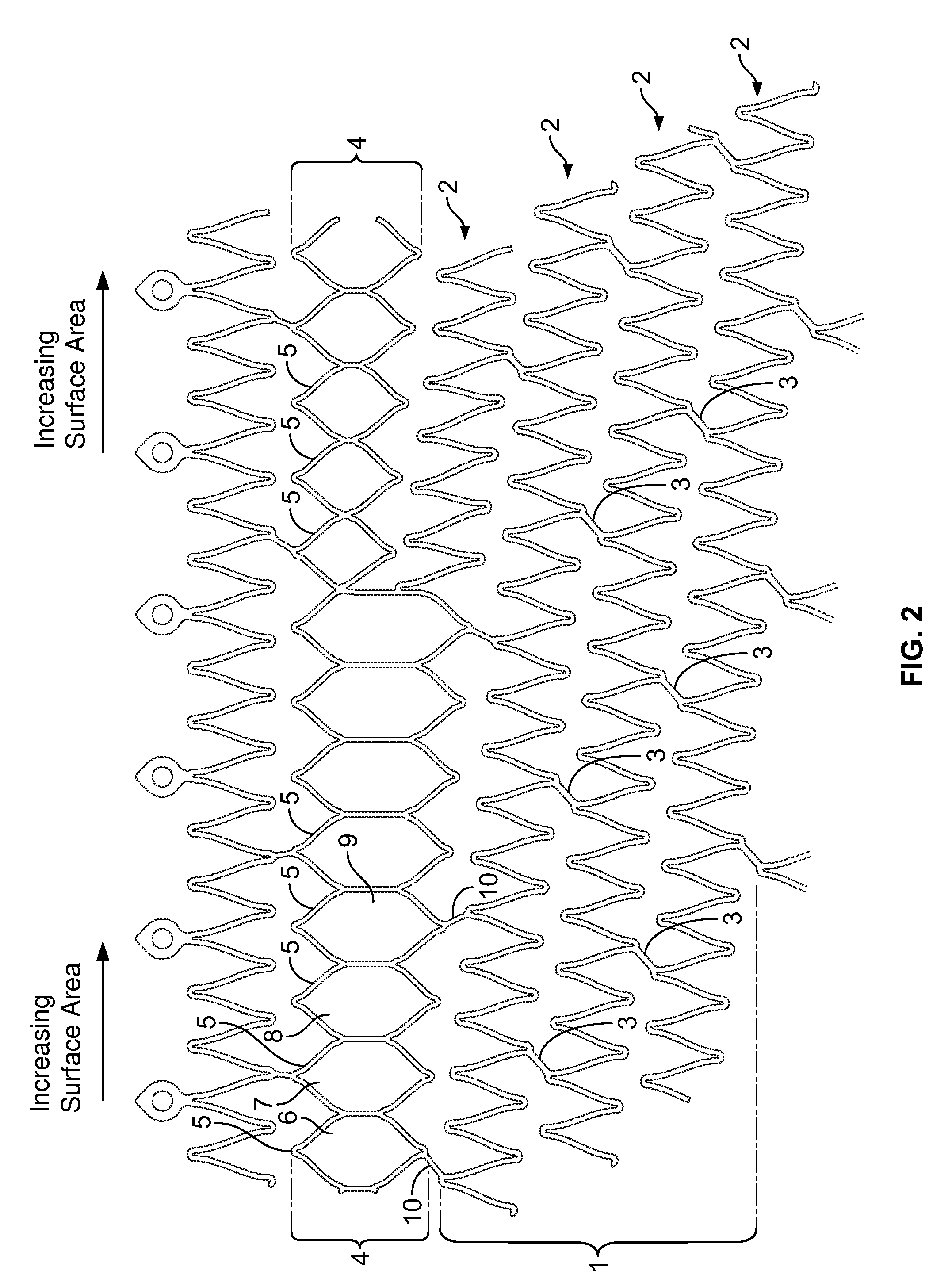
[0052]The self-expanding stent of the present invention provides for a transition zone between the main body of the stent and the end zone, comprising a plurality of n-sided polygons where the surface area of adjacent polygons in the transition zone is unequal. In one embodiment, the surface area of the polygons in the transition zone increases circumferentially across the transition zone around the long axis of the stent in a clockwise or counterclockwise manner. The polygons are formed from two pairs of undulations which are connected by a plurality of segments. The bending moment M of the undulations is equal within each polygon and remains constant across the transition zone, although the specific bending moment M depends on the length, thickness and width of the various segments forming each undulation.

[0053]The stent may be inserted into the lumen of any vessel or body cavity expanding its cross-sectional lumen. The invention may be deployed in any artery, vein, duct or other ...


PUM


Abstract

The self-expanding stent of the present invention provides for a transition zone between the main body of the stent and the end zone, comprising a plurality of n-sided polygons where the surface area of the adjacent polygons in the transition zone is unequal. In one embodiment, the surface area of the polygons in the transition zone increases circumferentially across the transition zone in a clockwise or counterclockwise manner. The polygons are formed from two pairs of undulations which are connected by segments. The bending moment of the undulations is equal within each polygon and constant across the transition zone.

Description

CROSS-REFERENCE RELATED APPLICATIONS[0001]This application claims the benefit of U.S. Provisional Application No. 61 / 178,139 filed May 14, 2009, and U.S. Provisional Application No. 61 / 223,435 filed Jul. 7, 2009BACKGROUND OF THE INVENTION[0002]Stents are scaffolds which are positioned in diseased vessel segments to support the vessel walls. During angioplasty, stents are used to repair and reconstruct blood vessels. Placement of a stent in the affected arterial segment prevents elastic recoil and closing of the artery. Stents also prevent local dissection of the artery along the medial layer. Physiologically, stents may be placed inside the lumen of any space, such as an artery, vein, bile duct, urinary tract, alimentary tract, tracheobronchial tree, cerebral aqueduct or genitourinary stent. Stents may also be placed inside the lumen of non-human animals, such as primates, horses, cows, pigs and sheep.[0003]In general, there are two types of stents: self-expanding and balloon-expand...

Claims


Application Information

Patent Timeline
Patent Type & Authority Applications(United States)
IPC IPC(8): A61F2/82
CPCA61F2/88A61F2/91A61F2/915A61F2250/0039A61F2002/91516A61F2002/91525A61F2002/91558A61F2002/91508
Inventor COTTONE, ROBERT J.YE, SHUSHENG
Why Eureka
Try Eureka