Power transmission mechanism and robot arm using the same

a technology of power transmission mechanism and robot arm, which is applied in the direction of gearing, mechanical control devices, instruments, etc., can solve the problems of further affecting the power transmission and service life of steel ropes, limited degree of freedom, etc., and achieve the effect of efficient transmission of power and prolonged service life of the robot arm

Active Publication Date: 2011-06-02
IND TECH RES INST
View PDF5 Cites 40 Cited by
  • Summary
  • Abstract
  • Description
  • Claims
  • Application Information

AI Technical Summary

Benefits of technology

[0012]In the power transmission mechanism and the robot arm using the same provided in the present invention, two power sources are transmitted to the joint component through the stopping component, so that the robot arm using steel ropes as a power transmission medium can achieve two-degree-of-freedom motions. Furthermore, the stopping component can efficiently transmit power according to the length of the support arm component without adjusting the tension of the steel ropes or sacrificing the power, and the service life of the robot arm is prolonged. Thus, the present invention provides an optimum design of the power transmission mechanism of the robot arm.

Problems solved by technology

A joint-type robot arm stopped by steel ropes in the prior art is limited by the relation of steel ropes in spatial arrangement and thus has limited degree-of-freedom.
Furthermore, the length of the support arm in the robot arm further influences the power transmission and service life of the steel ropes.

Method used


Image

  • Power transmission mechanism and robot arm using the same
  • Power transmission mechanism and robot arm using the same
  • Power transmission mechanism and robot arm using the same

Examples


Embodiment Construction

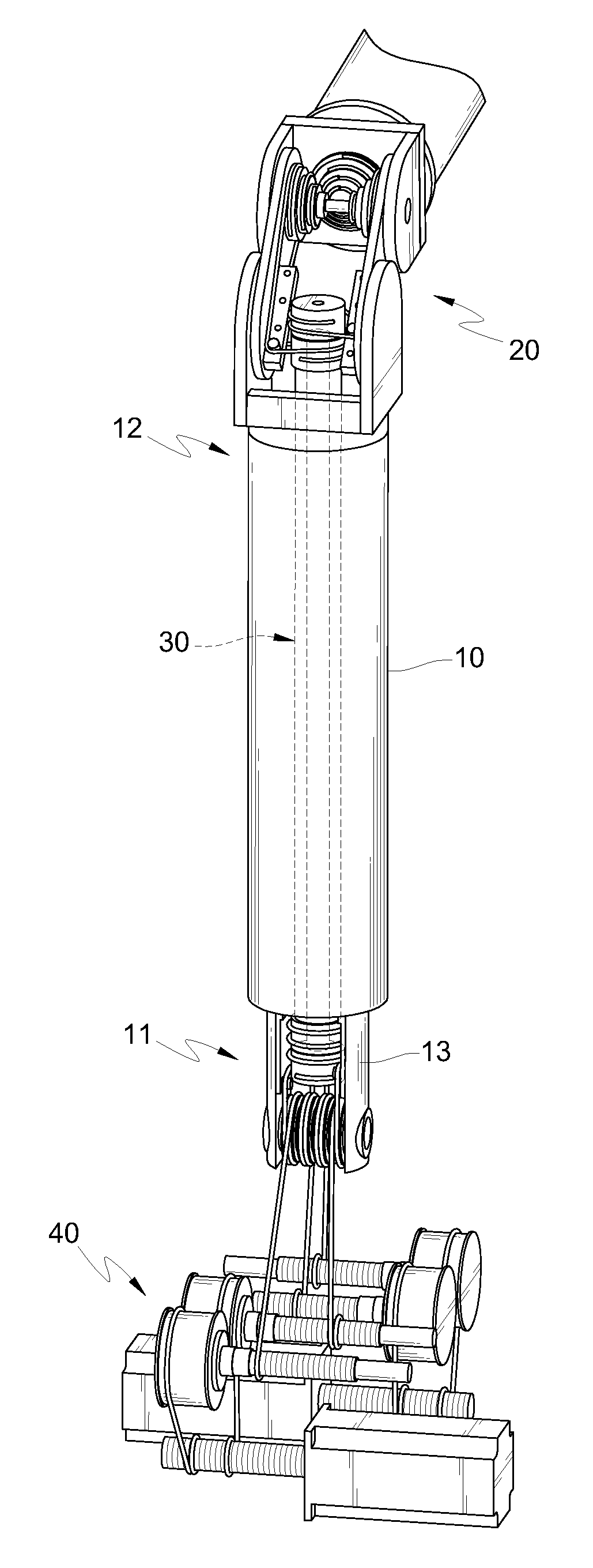
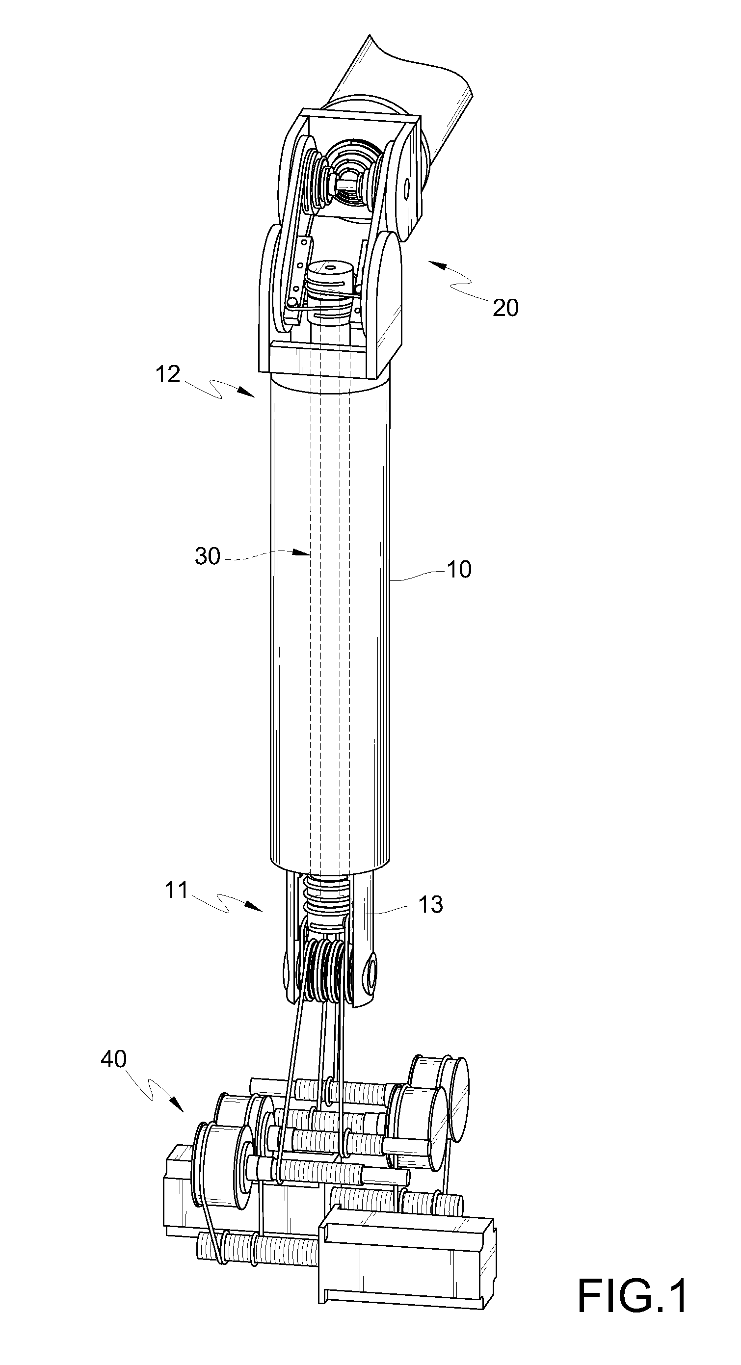
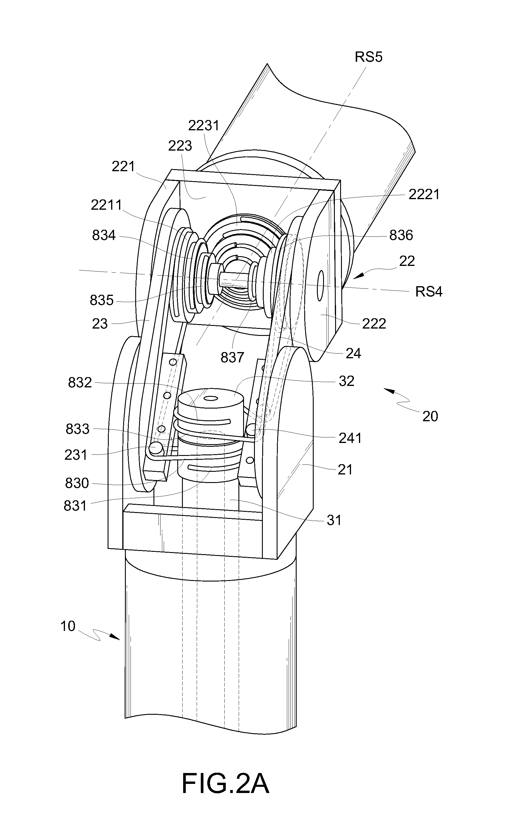
[0021]According to the power transmission mechanism and the robot arm using the same in the present invention, the robot arm is used for simulating actions of the human's arm, and is formed by a structure with a plurality of support arms connected together, and the robot arm is controlled through controlling the pivoting motions of each support arm. The robot arm for simulating the human's arm comprises a waist, a shoulder, an upper arm, an elbow, a fore arm, a wrist, a hand, and fingers. In the following specific embodiments, seven-degree-of-freedom motions are performed for the waist, the shoulder, the upper arm, the elbow, the fore arm, and the wrist. However, the technical features of the present invention are not limited to the following embodiments. Furthermore, each rotation means is mounted by bearings in the robot arm, which can be understood and implemented by those skilled in the art, and the bearings are not described in detail in the following disclosure of the present ...


PUM


Abstract

A power transmission mechanism and a robot arm using the same are described. The power transmission mechanism at least includes a first power source, a second power source, a plurality of steel ropes, a support arm component, a stopping component and a joint component. The stopping component is disposed in the support arm component and includes a first stopping unit and a second stopping unit that rotate coaxially. The first and second power sources and the joint component are disposed at two ends of the support arm component. The first and second power sources transmit power via the first stopping unit and the second stopping unit through the plurality of steel ropes to drive the joint component to perform a two-degree-of-freedom motion. The support arm component and the joint component can be applied in an upper arm and an elbow of a robot arm, thereby constituting a multi-degree-of-freedom robot arm.

Description

CROSS-REFERENCE TO RELATED APPLICATIONS[0001]This non-provisional application claims priority under 35 U.S.C. §119(a) on Patent Application No(s). 098140909 filed in Taiwan, R.O.C. on Nov. 30, 2009, the entire contents of which are hereby incorporated by reference.BACKGROUND OF THE INVENTION[0002]1. Field of Invention[0003]The present invention relates to a power transmission mechanism, and more particularly to a power transmission mechanism applied in a multi joint robot arm.[0004]2. Related Art[0005]The robot or robot arm has been widely applied in various different fields such as production and manufacturing, warehouse management, and intelligent nursing. The robot or robot arm is usually formed by a structure with a plurality of support arms connected together. The pivoting motion of each support arm is controlled by driving joints connecting the support arms.[0006]During motions of a robot arm, a joint is rotated by using a rotating power provided by a motor. The power of the m...

Claims


Application Information

Patent Timeline
Patent Type & Authority Applications(United States)
IPC IPC(8): B25J17/00F16H21/52B25J18/00
CPCB25J9/102B25J9/104F16H2019/0695Y10T74/20305Y10T74/20323Y10T74/18832Y10T74/20317
Inventor PAN, WEI LUNGHUANG, CHUN HUNGCHUNG, HSIANG NIEN
Owner IND TECH RES INST
Why Eureka
Try Eureka