Track and drive mechanism for a vehicle

a technology of drive mechanism and track, applied in the field of vehicles, can solve the problems of power loss, change in pitch length, and difficulty in matching, and achieve the effect of less power, less belt tension, and resisting dislodging or jumping

Inactive Publication Date: 2007-01-02
ASV HLDG INC
View PDF12 Cites 9 Cited by
  • Summary
  • Abstract
  • Description
  • Claims
  • Application Information

AI Technical Summary

Benefits of technology

[0014]Advantageously, the vehicle will travel over soft surfaces without causing damage to the surface. The drive belt having lugs which are designed to resist dislodging or jumping off the track so that less power is needed to drive the track for given loads. In addition, the track with the drive lugs needs a minimal amount of wrap around the circumference of the drive sprocket to stay engaged with the sprocket. The track requirement of a minimal amount of wrap, opens up the design possibilities. In addition, belt tension does not have to be tighten and maintained to make sure the belt stayed on the drive sprocket. The lesser belt tension lessens the amount of power needed. The lesser belt tension also lengthens the life of the belt. The sprocket and track with these drive lugs minimize “scrubbing” between the driving lugs and the sprocket driver. The sprocket is self cleaning and removes debris from the sprocket area to minimize problems associated with debris build up changing the pitch relationship between the sprocket and the flat track. The resulting vehicle is very effective in transmitting power to the surface over which it passes. The vehicle requires very low maintenance since is less prone to track derailment.

Problems solved by technology

One of the major design challenges with all types of tracks and vehicles is to find the most efficient way to transfer the torque of the drive mechanism to the track with minimum power loss.
The track tension also results in power loss.
In practice, proper matching is difficult to achieve since an elastomeric or rubber is resilient and can stretch or compress depending on a number of factors.
Another major cause of changes in pitch length occurs when a rubber tracked vehicle is turned.
Variations in the pitch length of the track results in a mismatch between the pitch length of the track and the pitch diameter of the sprocket.
This causes a loss in efficiency.
Scrubbing in or out can result in extreme power loss and excessive wear on the track drive lugs and sprocket teeth.
The use of sleeves, whether fixed and made of a low friction material or whether rotatable, many times will reduce the power loss due to the “scrubbing action” but generally gives rise to another problem.
This other problem is due to the fact that current drive lug designs incorporate the design starting point related to sprockets for metal tracks.
A problem occurs, however, in designs employing a sleeve in the drive sprocket.
A belt with such drive lugs may have a tendency to dislodge itself or jump out from the drive sprocket.
Each of these solutions increases the amount of friction needed to drive the belt and increases the amount of power needed to drive the belt.
In addition, the angle between the drive sprocket portion, such as a sleeve and the angled wall of the drive lug still presents an incline that the sleeve can “roll up” to dislodge.

Method used


Image

  • Track and drive mechanism for a vehicle
  • Track and drive mechanism for a vehicle
  • Track and drive mechanism for a vehicle

Examples


Embodiment Construction

[0028]In the following detailed description, reference is made to the accompanying drawings which form a part hereof, and in which are shown by way of illustration specific embodiments in which the invention may be practiced. It is to be understood that other embodiments may be utilized and structural changes may be made without departing from the scope of the present invention.

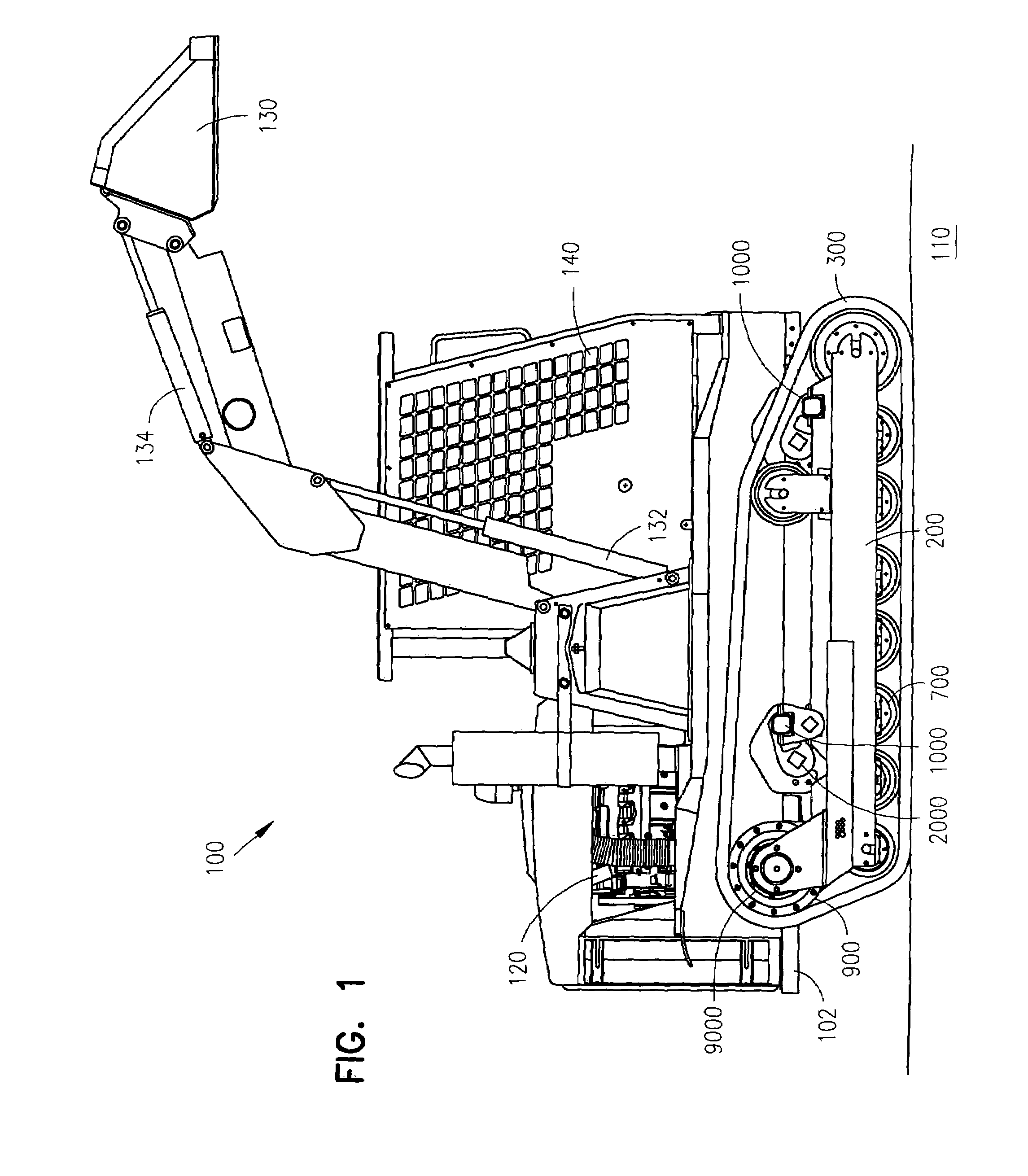
[0029]FIG. 1 shows a perspective view of an embodiment of the multi-surface vehicle 100 on a surface 110. The multi-surface vehicle 100 includes a body frame 102 which carries an engine 120 such as an eighty horsepower, 4.5 liter John Deere PowerTech Diesel or a one hundred fifteen horsepower, 4.5 liter John Deere PowerTech Turbo Diesel. Both of these engines are available from John Deere and Company of Moline, Illinois. The engine 120 powers a hydrostatic transmission which powers hydraulic drive motors with planetary gear boxes which eliminates additional chains and sprockets, thereby lessening the complexi...


PUM


Abstract

A tracked vehicle capable of traversing a variety of surfaces without damaging the surface traversed includes a track having an inner surface, an outer surface, and a pitch line between the inner surface and the outer surface. Driving lugs are attached to the inner surface of the track. The vehicle also includes a driver sprocket assembly having a number of driving portions for engaging the driving lugs to drive the track. Each drive lug has at least one angled sidewall which, as the drive lug is engaged with the drive portion, presents a wall either substantially parallel to a line between the axis of rotation of the sprocket and the driving portion of the sprocket or slightly declined with respect to a line between the axis of rotation of the sprocket and the driving portion of the sprocket.

Description

RELATED APPLICATION[0001]This application claims priority under 35 U.S.C. 119(e) from U.S. Provisional Application Ser. No. 60 / 392,393 filed Jun. 28, 2002, which application is incorporated herein by reference.FIELD OF THE INVENTION[0002]The invention is related to a vehicle which uses a track to traverse various terrains. Specifically, the invention relates to a track and drive mechanism associated with a multi-surface vehicle with a driver and an elastomeric track having drive lugs.BACKGROUND OF THE INVENTION[0003]A variety of track driven vehicles have been around for many years. Tracked vehicles vary from 100 ton military tanks and bull-dozers to 300 pound snowmobiles. Track types vary from segmented steel tracks to one piece molded rubber tracks.[0004]One of the major design challenges with all types of tracks and vehicles is to find the most efficient way to transfer the torque of the drive mechanism to the track with minimum power loss. There are many torque transmission syst...

Claims


Application Information

Patent Timeline
Patent Type & Authority Patents(United States)
IPC IPC(8): B62D55/12F16H57/00B62D55/108B62D55/125B62D55/24
CPCB62D55/1083B62D55/24B62D55/125
Inventor SAFE, CARYLEMKE, BRAD
Owner ASV HLDG INC
Why Eureka
Try Eureka