Feeder waveguide and sector antenna

a feeder waveguide and antenna technology, applied in waveguide type devices, antennas, basic electric elements, etc., can solve the problems of inability to point-to-multipoint communication, shorten communication distance, poor usability, etc., to reduce power leakage, implement data transmission efficiently, and reduce power leakage

Inactive Publication Date: 2006-11-02
NEC CORP
View PDF8 Cites 1 Cited by
  • Summary
  • Abstract
  • Description
  • Claims
  • Application Information

AI Technical Summary

Benefits of technology

[0020] The sector antenna of the present invention is characterized in that it uses the above-described feeder waveguide as a feeder waveguide to a plurality of antennas each having directivity in a different direction. In this feeder waveguide, as described in the foregoing explanation, transmission power can be conducted to a selected branch waveguide while reducing the leakage of power to nonselected branch waveguides and the adverse effect of reflected waves from nonselected branch waveguides, and as a result, the sector antenna of the present invention can implement data transmission efficiently and with few errors.
[0021] In addition, a feeder waveguide can be formed from waveguide tubes, whereby the sector antenna of the present invention can be applied to ultra high-speed communication that uses electromagnetic waves of short wavelength such as millimeter waves. In particular, as described in the foregoing explanation, a construction in which rows of conductive vias and the metal layer in a dielectric board are used to form waveguide tubes facilitates the formation of a desired feeder waveguide as a planar circuit and then it facilitates the construction of a planar sector antenna.
[0022] As described in the foregoing explanation, the present invention can reduce both the leakage of power to nonselected branch waveguides and the adverse effects caused by reflected waves from nonselected branch waveguides in a feeder waveguide having branches, and further, enables the effective transmission of transmission power to only selected branch waveguides that is both efficient, and moreover, virtually free of the influence of reflection.
[0023] In the present invention, a waveguide can be formed from waveguide tubes, whereby the transmission of electromagnetic waves of short wavelength such as millimeter waves can be realized with low loss. In addition, virtually no effect of reflection occurs in the above-described waveguide tubes, whereby data transmission can be realized with few errors. The waveguide of the present invention can therefore be advantageously used in ultra high-speed radio communication.
[0024] A sector antenna that uses this type of feeder waveguide of the present invention can supply an antenna radiation beam in a selected direction at low loss and free of the effects of reflection and can realize data transmission at ultra high speed with few errors. In addition, the use of this sector antenna facilitates the alignment of the antenna direction and thus enables the implementation of point-to-multipoint communication.

Problems solved by technology

The antenna of the form shown in FIGS. 1A and 1B is disadvantageous in that it has poor usability such that it requires directional alignment of the antenna and is incapable of point-to-multipoint communication.
However, a sector antenna in which antennas are merely integrated has the drawback that transmission power is dispersed in each of the sectors, resulting in a shortening of the communication distance.
However, in the configuration of the example of the prior art that is described with reference to FIG. 2, the existence of the long feeder distribution paths 73 up to the selection structure for each sector, i.e., MMICs 74, results in leakage of transmission power to feeder distribution paths 73 other than that of feeder distribution path 73 to the selected sector and thus reduces the effective transmission power.
There is the further disadvantage that the signal wave is reflected in MMICs 74 that are cut off, and these reflected signal waves interfere with and adversely affect the signal wave that is sent to the selected sector.

Method used


Image

  • Feeder waveguide and sector antenna
  • Feeder waveguide and sector antenna
  • Feeder waveguide and sector antenna

Examples


Embodiment Construction

[0035] The following explanation regards an embodiment of the present invention with reference to the accompanying drawings.

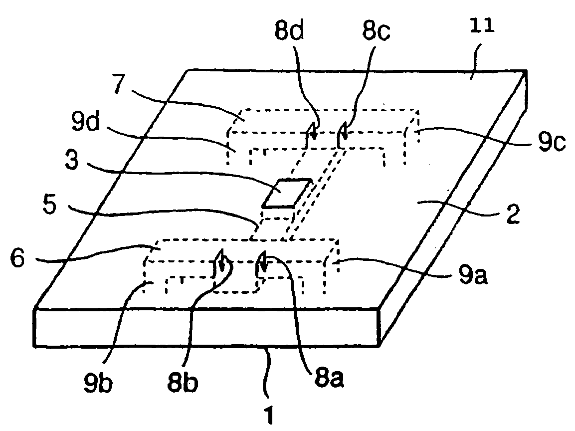
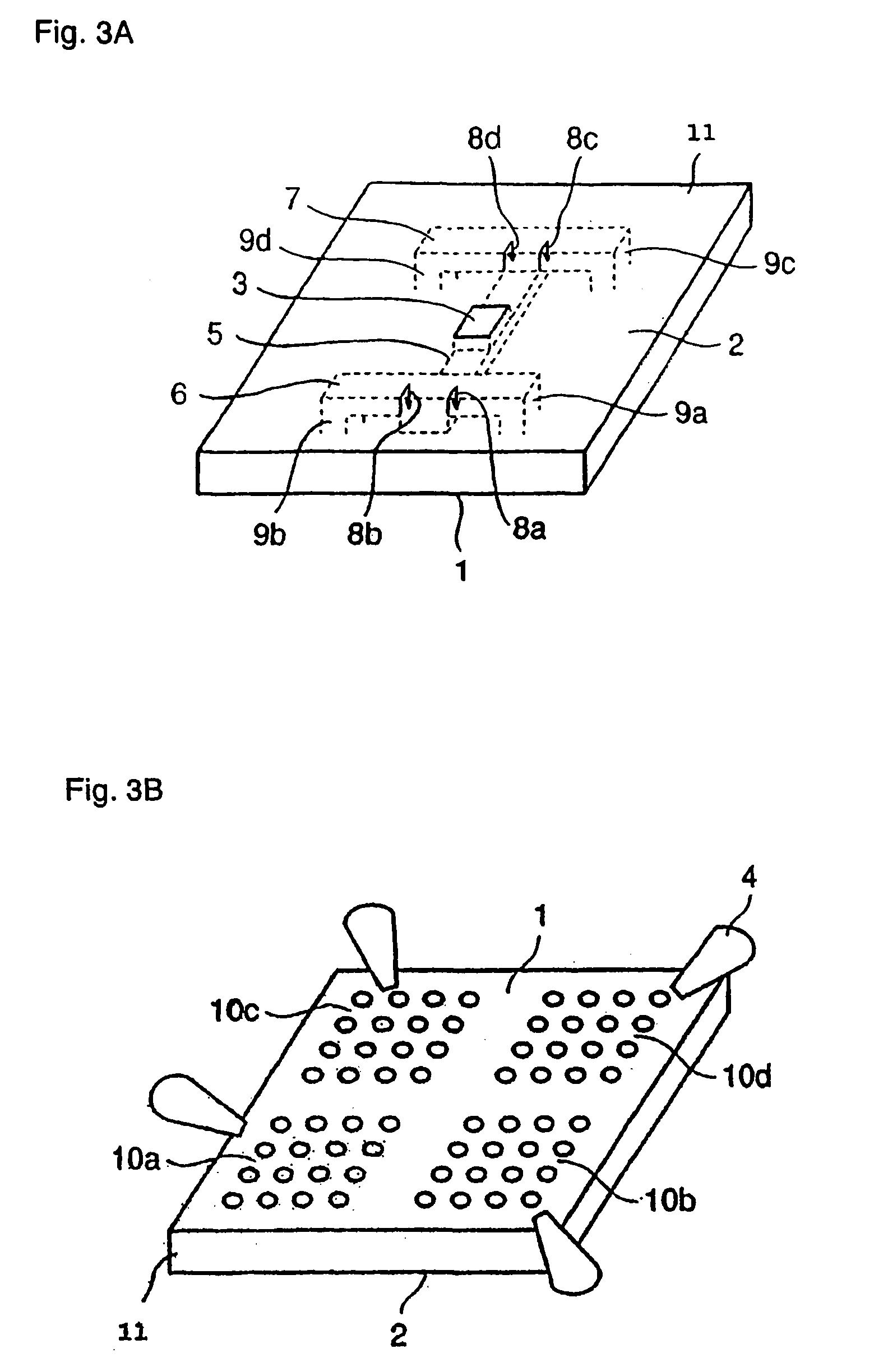
[0036]FIGS. 3A and 3B are schematic views of a feeder waveguide according to an embodiment of the present invention and a sector antenna that is provided with this feeder waveguide. The sector antenna of the present embodiment is a planar antenna in which feeder port 3 is formed on one surface of dielectric board 11 and antenna elements are formed on the other surface; FIG. 3A being a perspective view as seen from the side of feeder surface 2 and FIG. 3B being a perspective view as seen from the side of antenna radiation surface 1.

[0037] In this sector antenna, a plurality of round elements is formed as antenna elements. These antenna elements are formed aligned in arrays in each of four regions, whereby the rectangular antenna radiation surface 1 can be split in two in both the vertical and horizontal directions. The antenna elements that are formed in each ...


PUM


Abstract

In the sector antenna of the present invention, a feeder waveguide is formed that branches midway from a feeder port to each of a plurality of antennas. This feeder waveguide is formed from a waveguide tube and includes a main feeder line that extends from a waveguide that extends from the feeder port and branches in two directions, and branch feeder lines that each branch in two directions from the two ends of the main feeder line. Sector selection structures are provided for selectively shutting off each branch waveguide by effectively forming conductive walls for blocking the cross section of each of the branch waveguides at positions of each of the branch feeder lines that branch and extend from the main feeder line and from which each branch waveguide begins.

Description

TECHNICAL FIELD [0001] The present invention relates to a feeder waveguide that is used in a radio communication device for microwave and millimeter wave bands and to a sector antenna that uses the feeder waveguide. BACKGROUND ART [0002] In recent years, ultra high-speed radio communication systems such as wireless LAN or communication systems according to the IEEE 1394 standards have been realized that are capable of multimedia data transmission that includes moving pictures. Such systems are required to realize ultra high-speed data transmission of at least 100 Mbps at a low error rate. In order to avoid the occurrence of adverse influence upon communication resulting from multipath propagation, narrow-beam antennas are used and point-to-point communication is realized from a specific location to a specific location. [0003]FIGS. 1A and 1B show a schematic view of a narrow-beam antenna of the prior art. This antenna is a planar antenna in which feeder port 53 is formed on one surfa...

Claims


Application Information

Patent Timeline
Patent Type & Authority Applications(United States)
IPC IPC(8): H01Q13/00H01P1/15
CPCH01P1/15
Inventor OHATA, KEIICHIITO, MASAHARUKISHIMOTO, SHUYAMARUHASHI, KENICHI
Owner NEC CORP
Why Eureka
Try Eureka