Wireless power transmission system

a power transmission system and wireless technology, applied in the direction of transformers/inductance circuits, basic electric elements, inductances, etc., can solve the problems of long charging time, inefficient power transmission, and difficulty in reducing the size of devices, so as to suppress the generation of eddy current, reduce the size of power transmission devices, and reduce the size of power reception devices

Active Publication Date: 2016-02-11
MURATA MFG CO LTD
View PDF3 Cites 7 Cited by
  • Summary
  • Abstract
  • Description
  • Claims
  • Application Information

AI Technical Summary

Benefits of technology

[0020]With this configuration, the area occupied by the electrodes and coils in the power reception device and the power transmission device can be reduced.
[0021]It is preferable that the first power-transmission-side electrode and the second power-transmission-side electrode, and the first power-reception-side electrode and the second power-reception-side electrode have a shape that suppresses generation of eddy currents.
[0022]With this configuration, by suppressing the generation of eddy currents in the electrodes, canceling out of a magnetic field by an eddy current generated by an electrode can be prevented.
[0023]According to the present invention, by utilizing both electric-field coupling and magnetic-field coupling, the efficiency with which power is transmitted from a power transmission device to a power reception device can be increased.

Problems solved by technology

In addition, coils are utilized and therefore it difficult to reduce the size of the devices.
When the power reception device is for example a tablet terminal in which the secondary battery has a large charging capacity, there is a problem that the charging time is long when power transmission is not efficiently performed.

Method used


Image

  • Wireless power transmission system
  • Wireless power transmission system
  • Wireless power transmission system

Examples


embodiment 1

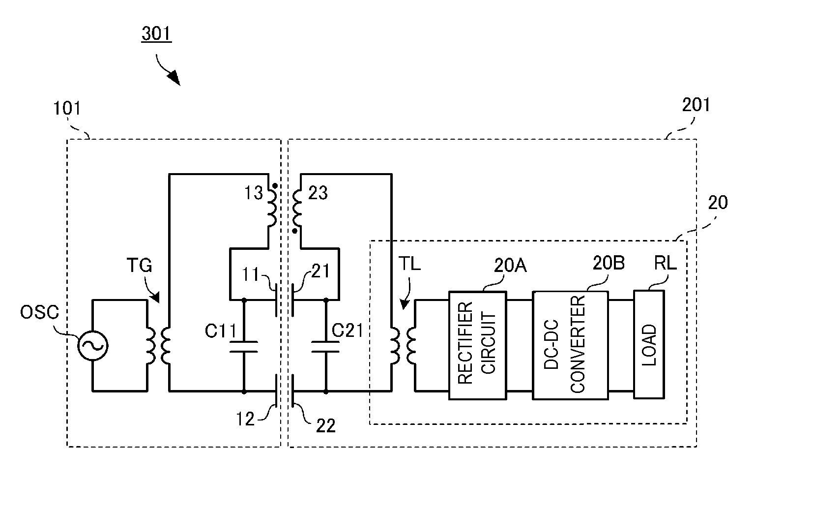
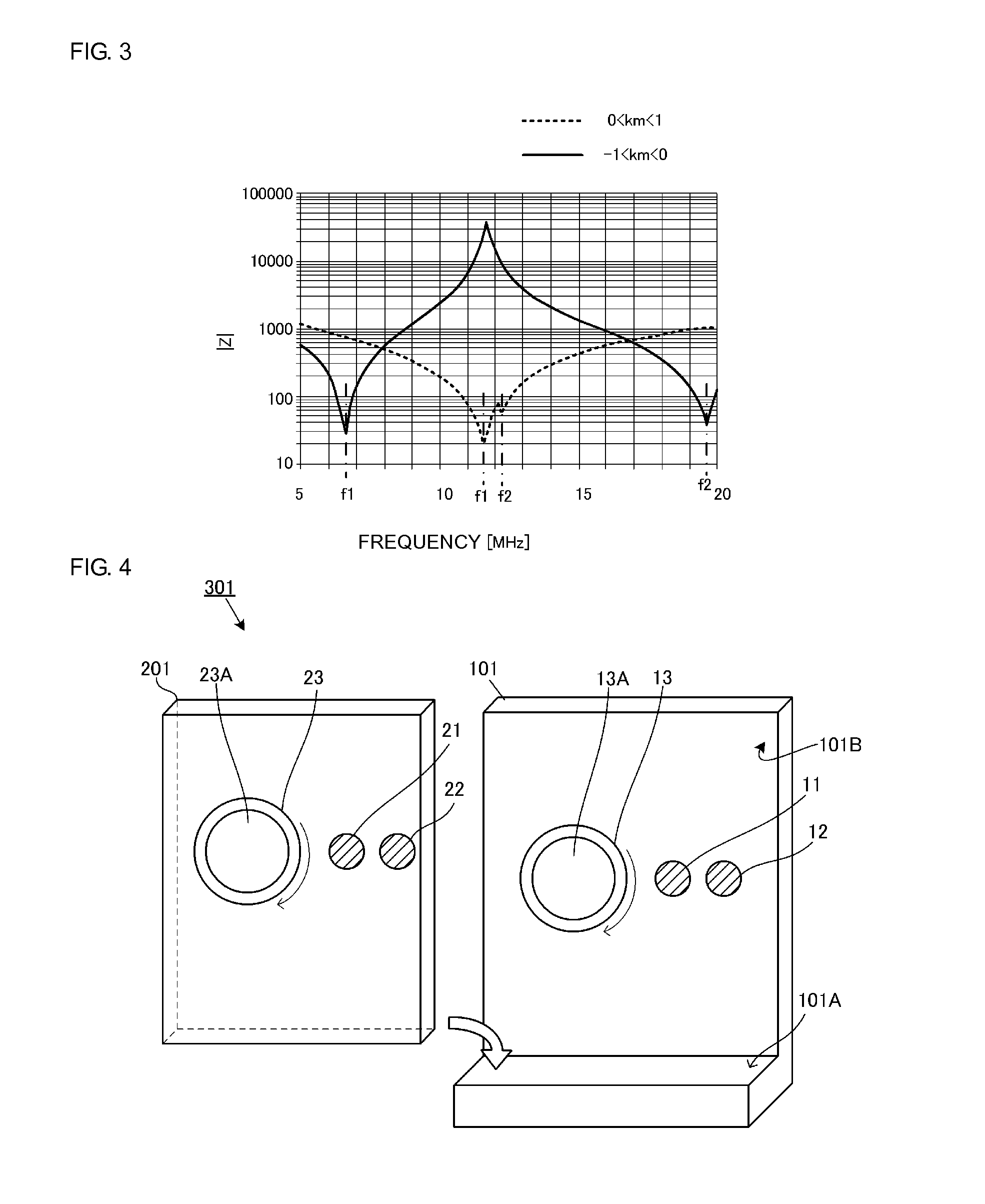
[0060]FIG. 4 is a perspective view illustrating a power transmission device and a power reception device of a wireless power transmission system 301 according to Embodiment 1. Active electrodes 11 and 21, passive electrodes 12 and 22 and planar coils 13 and 23 are provided inside casings of a power transmission device 101 and a power reception device 201 and these casings are illustrated in a see-through manner in FIG. 4.

[0061]The power reception device 201 of the wireless power transmission system 301 is a mobile electronic appliance equipped with a battery module including a secondary battery, a charging circuit and so forth. Examples of such a mobile electronic appliance include cellular phones, portable music players, laptop PCs, digital cameras and so forth. The power reception device 201 is mounted on the power transmission device 101 and the power transmission device 101 charges the secondary battery of the power reception device 201.

[0062]The power transmission device 101 ha...

embodiment 2

[0082]Hereafter, Embodiment 2 of the present invention will be described. In this embodiment, the shapes of the active electrodes and the passive electrodes of the power transmission device and power reception device are different to those in Embodiment 1. This difference will be described hereafter.

[0083]FIG. 7 is a perspective view illustrating a power transmission device 102 and a power reception device 202 of a wireless power transmission system 302 according to Embodiment 2. FIG. 8 is a sectional view illustrating the positional relationship between active electrodes 14 and 24, passive electrodes 15 and 25 and planar coils 13 and 23 when the power reception device 202 is mounted on the power transmission device 102.

[0084]The power transmission device 102 includes the planar coil 13, the circular active electrode 14 and the annular passive electrode 15 provided along a backrest surface 101B. The planar coil 13, the active electrode 14 and the passive electrode 15 are provided su...

embodiment 3

[0089]Hereafter, Embodiment 3 of the present invention will be described. In this embodiment, the configurations of the magnetic-field-coupled coils and the active electrodes and passive electrodes of the power transmission device and power reception device are different to those in Embodiment 1. This difference will be described hereafter.

[0090]FIG. 9 is a circuit diagram of a wireless power transmission system 303 according to Embodiment 3.

[0091]In this embodiment, a first coil 18A and a second coil 18B are connected to an active electrode 16 and a passive electrode 17 in a power transmission device 103. The first coil 18A and the second coil 18B form an LC resonance circuit with a capacitor C11 and so forth. The first coil 18A and the second coil 18B are connected to a secondary coil L12 of a step-up transformer TG and the first coil 18A, the second coil 18B and the secondary coil L12 form a single coil (hereafter, referred to as power-transmission-side coil). The active electrod...


PUM


Abstract

A wireless power transmission system includes a power transmission device, which applies an alternating-current voltage to active and passive electrodes, and a power reception device, which supplies to a load a voltage induced in active and passive electrodes facing the active and passive electrodes of the power transmission device. The power transmission device includes a planar coil connected to the active and passive electrodes and the power reception device includes a planar coil connected to the active and passive electrodes. Magnetic flux generated by the planar coils link with each other causing the planar coils to be magnetic-field coupled with each other. Thus, a wireless power transmission system capable of efficiently transmitting power is provided.

Description

CROSS REFERENCE TO RELATED APPLICATIONS[0001]The present application is a continuation of PCT / JP2014 / 067325 filed Jun. 30, 2014, which claims priority to Japanese Patent Application No. 2013-137683, filed Jul. 1, 2013, the entire contents of each of which are incorporated herein by reference.FIELD OF THE INVENTION[0002]The present invention relates to a wireless power transmission system in which power is wirelessly transmitted from a power transmission device to a power reception device.BACKGROUND OF THE INVENTION[0003]As a representative example of a wireless power transmission system, a magnetic-field-coupling-method power transmission system is known in which power is transmitted by utilizing a magnetic field from a primary coil of a power transmission device to a secondary coil of a power reception device. In this system, when power is transmitted by magnetic field coupling, the magnitude of the magnetic flux passing through each coil greatly affects the electromotive force and...

Claims


Application Information

Patent Timeline
Patent Type & Authority Applications(United States)
IPC IPC(8): H02J5/00
CPCH02J5/005H02J50/12H02J50/05H02J50/402
Inventor ICHIKAWA, KEIICHI
Owner MURATA MFG CO LTD
Why Eureka
Try Eureka