Resin gear

a technology of reinforced gear and friction, which is applied in the direction of gearing, gearing elements, hoisting equipment, etc., can solve the problems of insufficient reduction of sound between the teeth on the driven side and the teeth on the driving side, and insufficient reduction of so as to achieve effective absorbing, reduce friction noise resulting from the sliding of the tooth surface, and reduce the effect of noise during rotative power transmission

Inactive Publication Date: 2008-10-02
ENPLAS CORP
View PDF12 Cites 29 Cited by
  • Summary
  • Abstract
  • Description
  • Claims
  • Application Information

AI Technical Summary

Benefits of technology

[0009]In the invention, the contacting section between the resin gear and the mating gear on the tooth crest side of the tooth profile modification area is point-like and becomes elastically deformed. Therefore, impact occurring during meshing of the teeth is effectively absorbed. In the invention, the tooth width direction length of the contacting section between the tooth of the resin gear and the tooth of the mating gear becomes shorter as the sliding speed with the tooth surface of the meshing mating gear increases. Therefore, friction noise resulting from the sliding of the tooth surfaces can be reduced. As a result, in the invention, noise during rotative power transmission can be effectively reduced and the tooth of the resin gear can mesh with the tooth of the mating gear along the involute curved line from the tooth crest to the tooth root. Rotation transmission can be performed quietly and accurately.

Problems solved by technology

Noise resulting from a collision sound between the teeth on the driven side and the teeth on the driving side cannot be sufficiently reduced.
Noise resulting from the sliding of the tooth 104 cannot be sufficiently reduced.

Method used


Image

  • Resin gear
  • Resin gear
  • Resin gear

Examples


first embodiment

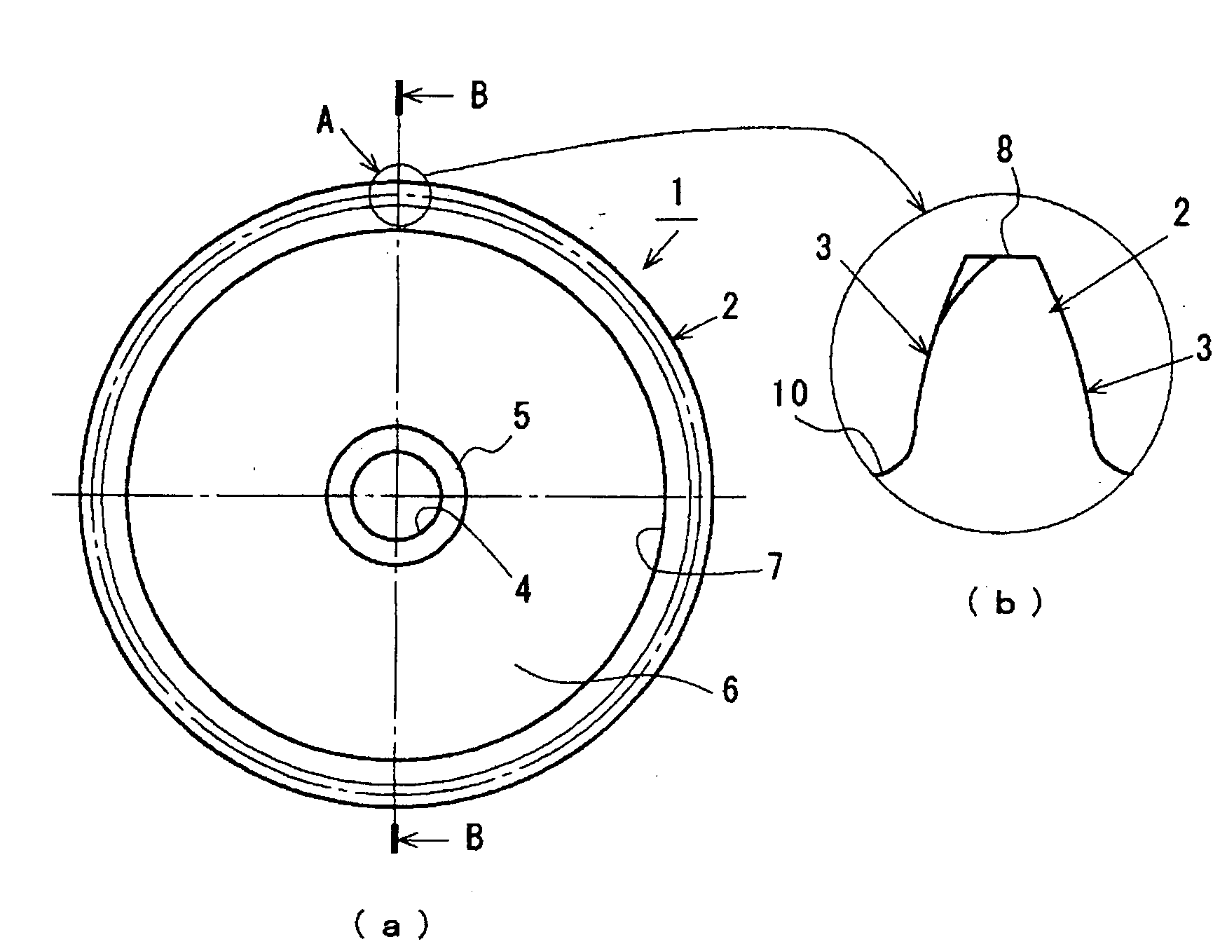
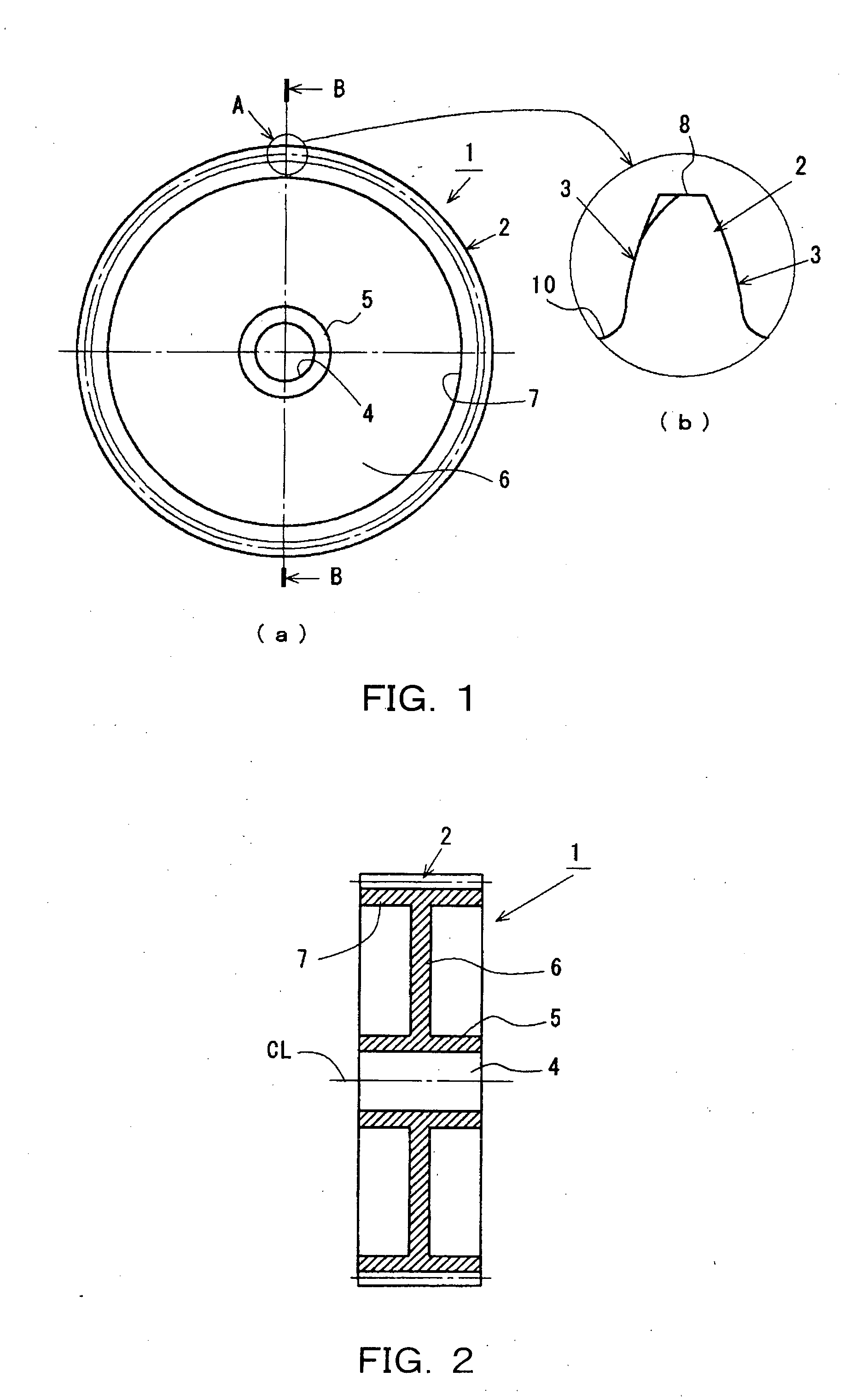
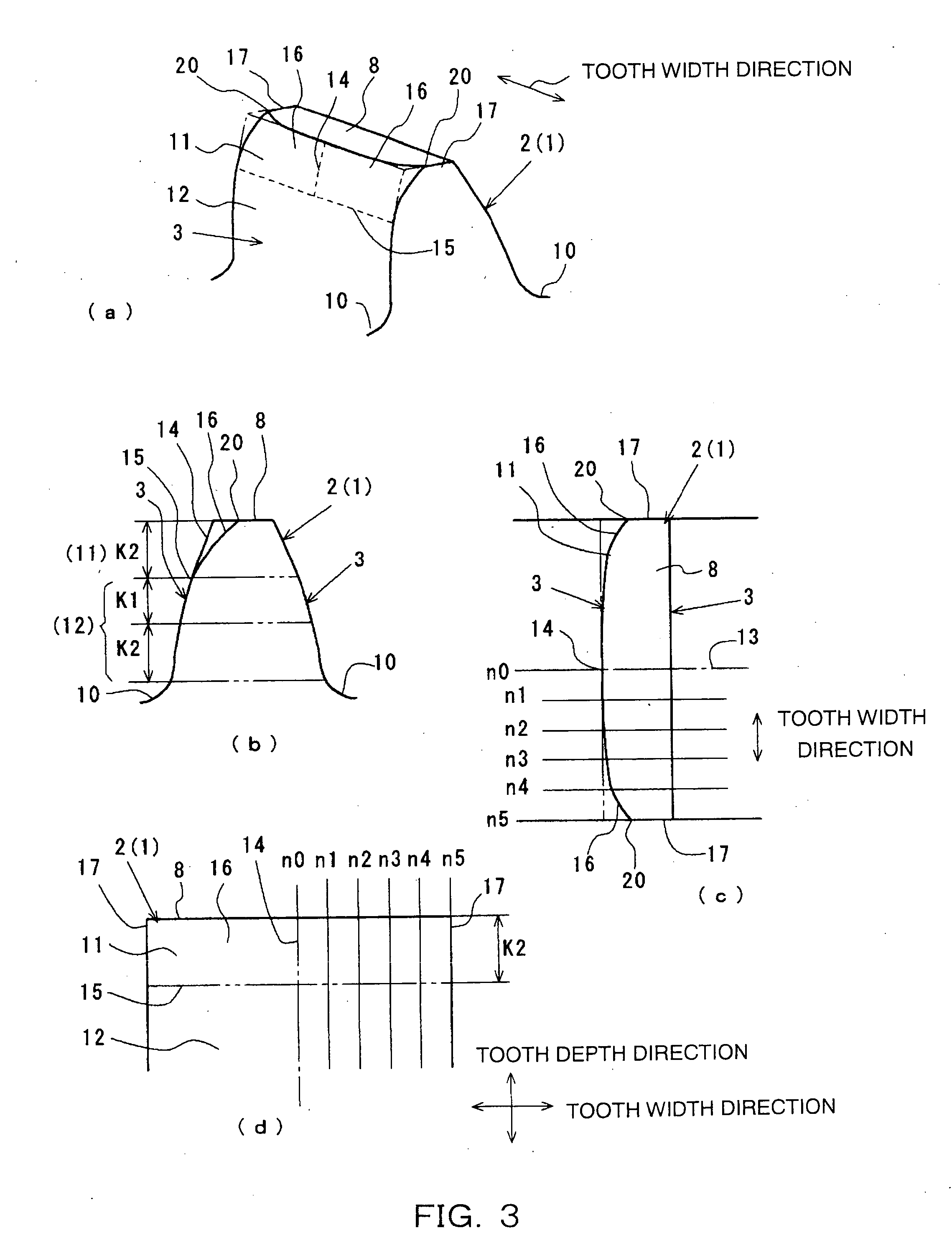
[0028]FIG. 1A is a front view of a resin spur gear 1 according to a first embodiment of the present invention. FIG. 1B is an enlarged view of section A in FIG. 1A (enlarged view of a front surface side of a tooth 2). FIG. 2 is a cross-sectional view of FIG. 1 taken along line B-B. FIG. 3 is an enlarged view of the tooth 2. In FIG. 3, FIG. 3A is a perspective view of an outer appearance of the tooth 2. FIG. 3B is a front view of the tooth 2. FIG. 3C is a planar view of the tooth 2. FIG. 3D is a side view of the tooth 2 viewed from a direction perpendicular to a tooth width direction of the tooth 2 (tooth surface 3 side).

[0029]As shown in the diagrams, the resin spur gear 1 according to the embodiment is formed from a resin material, such as polyacetal, polyamide, polyphenylene sulfide, and polybutylene terephthalate. The resin spur gear 1 includes a cylindrical section 5, a disc-shaped web 6, and a cylindrical rim 7. The cylindrical section 5 has an axis hole 4 in the center. The web...

second embodiment

[0048]A resin spur gear 1 according to a second embodiment will be described with reference to FIG. 8 to FIG. 9. FIG. 8 corresponds to FIG. 3 according to the first embodiment. FIG. 9 corresponds to FIG. 4 according to the first embodiment. Constituent elements in the resin spur gear 1 according to the embodiment that are the same as those in the resin spur gear 1 according to the first embodiment are given the same reference numbers. Explanations that are the same as those according to the first embodiment are omitted.

[0049]The tooth profile modification area 11 of the tooth 2 on the resin spur gear 1 in FIG. 8 includes the linear standard profile portion 14 and the profile modification portion 16, as does the resin spur gear1 according to the first embodiment. In the standard profile portion 14, the center 13 in the tooth width direction is formed by an involuted curved line from the tooth crest 8 to the involute profile area 12 side along the tooth depth direction. In the profile...

third embodiment

[0057]A resin spur gear 1 according to a third embodiment of the invention will be described with reference to FIG. 10 and FIG. 11. FIG. 10 is a diagram corresponding with FIG. 3 according to the first embodiment. FIG. 11 is a diagram corresponding with FIG. 4 according to the first embodiment. Constituent elements in the resin spur gear 1 according to the embodiment that are the same as those in the resin spur gear 1 according to the first embodiment are given the same reference numbers. Explanations that are the same as those according to the first embodiment are omitted.

[0058]The tooth profile modification area 11 of the tooth 2 on the resin spur gear 1 in the diagrams includes the linear standard profile portion 14 and the profile modification portion 16, as does the resin spur gear 1 according to the first embodiment. In the standard profile portion 14, the center 13 in the tooth width direction is formed by an involuted curved line from the tooth crest 8 to the involute profil...


PUM


Abstract

Noise can be effectively reduced without rotative power transmission accuracy being compromised.
In a tooth 2 of a resin gear 1, a tooth face that is a predetermined area from a tooth crest 8 towards a tooth root 10 side serves as a tooth profile modification area 11. A tooth surface excluding the tooth profile modification area 11 serves as an involute profile area 12. The tooth profile modification area 11 includes a linear standard profile portion 14 formed by an involute curved line from the tooth crest 8 of the tooth towards the tooth root 10 side and a profile modification portion 16 in which a tooth thickness gradually and smoothly decreases from the standard profile portion 14 along a tooth width direction and the tooth thickness gradually and smoothly decreases from a tooth root end side 15 towards the tooth crest 8. In the tooth profile modification area 11, a contacting section becomes elastically deformed as a result of the resin gear coming into contact with a meshing mating gear. A tooth width direction length of the contact surface gradually increases from a minute, point-like width to a full tooth width from the tooth crest 8 side towards the tooth root 10 side.

Description

BACKGROUND OF THE INVENTION[0001]1. Field of the Invention[0002]The present invention relates to a resin gear that transmits rotative power.[0003]2. Description of the Related Art[0004]Conventionally, a following resin spur gear 106 configured to reduce rotation transmission error and noise is known (refer to Patent Literature 1). As shown in FIG. 16 and FIG. 17, a tooth surface 103 of a two-pair meshing area 102 on a tooth crest 101 side is cut such that a rigidity of a tooth 104 in the two-pair meshing area 102 on the tooth crest side 101 is less than a rigidity of a tooth on a standard involute spur gear (referred to, hereinafter, as a spur gear). Difference between an amount of deformation in a one-pair meshing area 105 of the tooth 104 and an amount of deformation in the two-pair meshing area 102 of the tooth 104 is reduced. Patent Literature 1: Japanese Patent Laid-open Publication No. Heisei 8-312755 (refer, in particular, to FIG. 1 to FIG. 3).[0005]However, when the conventi...

Claims


Application Information

Patent Timeline
Patent Type & Authority Applications(United States)
IPC IPC(8): F16H55/17F16H1/00
CPCF16H55/088Y10T74/19972F16H55/0886
Inventor TAKUMORI, TORU
Owner ENPLAS CORP
Why Eureka
Try Eureka