Power transmitting apparatuses

a power transmission apparatus and power technology, applied in the direction of fluid couplings, gearings, couplings, etc., can solve the problems of reducing the available options for laying out the torque converter, increasing the size of the torque converter, etc., to achieve the effect of reducing the size of simplifying the power transmission apparatus, and reducing the size of the whol

Inactive Publication Date: 2011-12-22
FCC KK
View PDF7 Cites 1 Cited by
  • Summary
  • Abstract
  • Description
  • Claims
  • Application Information

AI Technical Summary

Benefits of technology

In embodiments where the clutch mechanism comprises the first clutch device, the second clutch device, and two hydraulic pistons corresponding respectively to the first and second clutch devices all contained in a same housing and the first and second clutch devices can be selectively actuated by controlling the hydraulic pressure for actuating the hydraulic pistons, the power transmitting apparatus can be simplified and the size of whole the power transmitting apparatus can be reduced.
In embodiments where the power transmitting apparatus comprises an automatic variable speed unit configured to transmit power between the clutch mechanism and the wheels, it is possible to easily achieve a preferable driving force as well as a vehicle operation condition that improves fuel consumption.
In embodiments where the automatic variable speed unit comprises a continuously variable speed unit, the driving force and vehicle operation conditions can be continuously adjusted to efficiently achieve the preferable driving force as well as a vehicle operating condition that improve fuel consumption.

Problems solved by technology

For example, in the above-noted known combination-type apparatus, a lock-up clutch that is movable between the connected position and the non-connected position in the hydraulic atmosphere within the torque converter increases the size of torque converter as well as restricts the available options for laying out the torque converter.

Method used


Image

  • Power transmitting apparatuses
  • Power transmitting apparatuses
  • Power transmitting apparatuses

Examples


Embodiment Construction

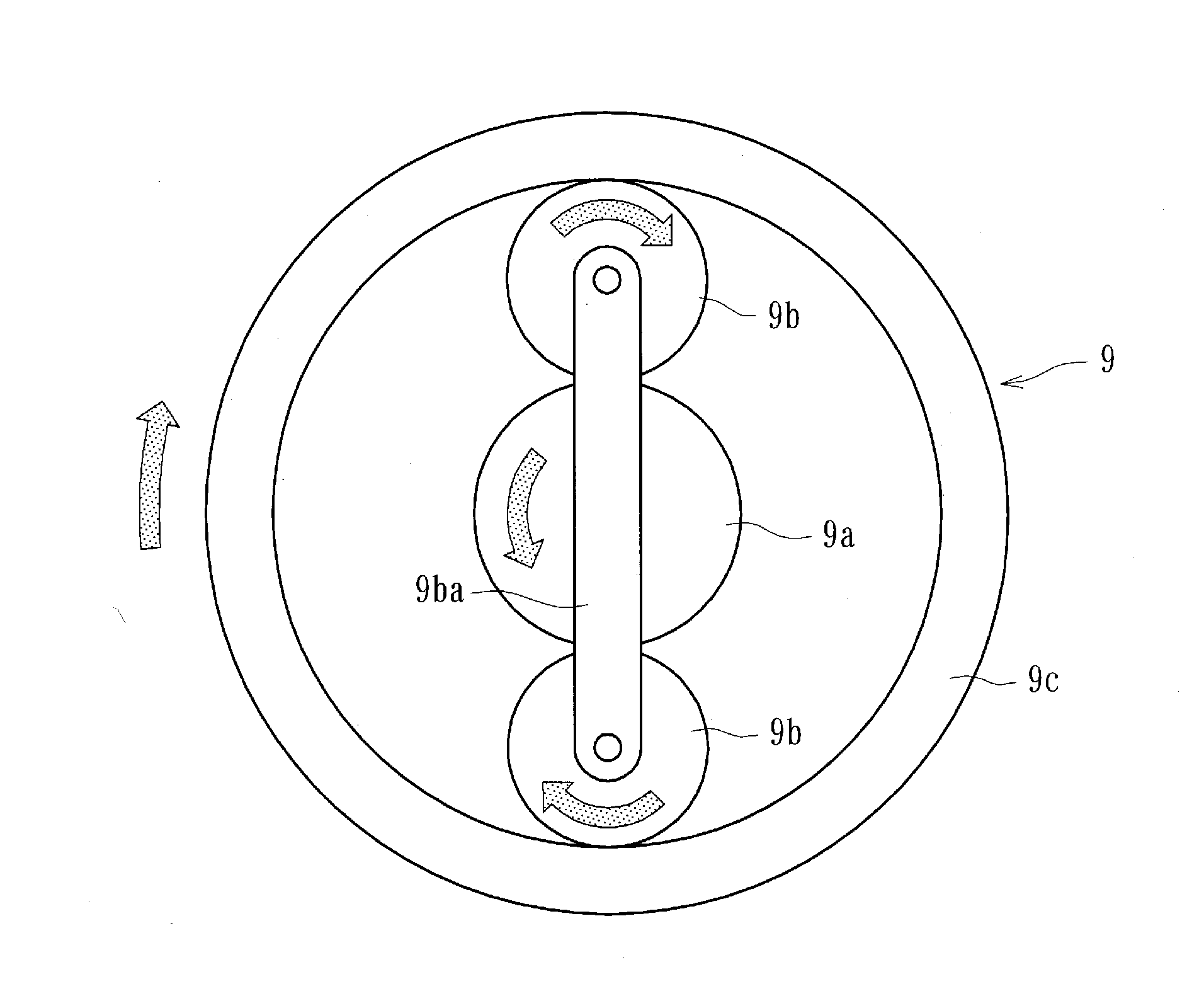
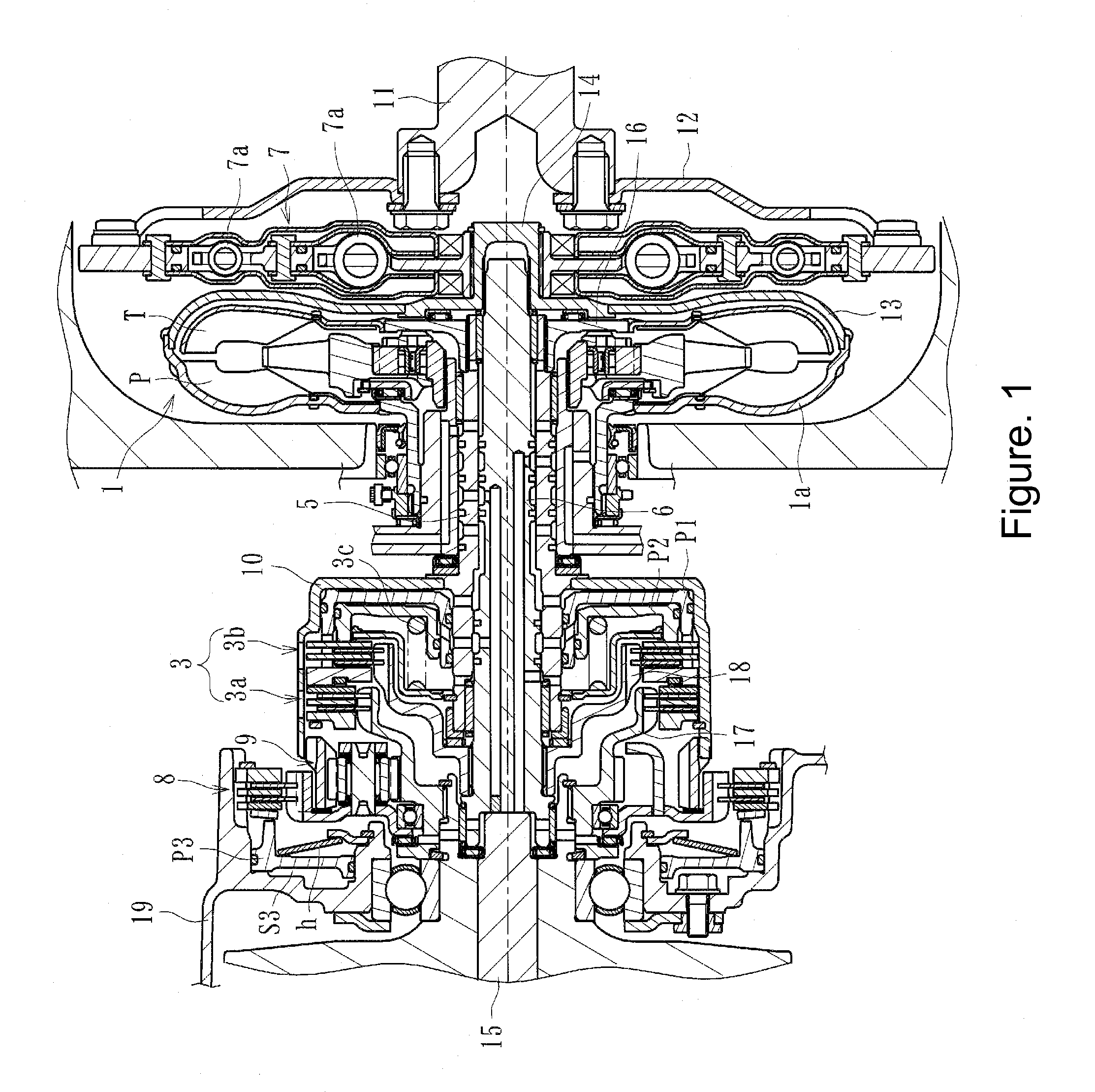
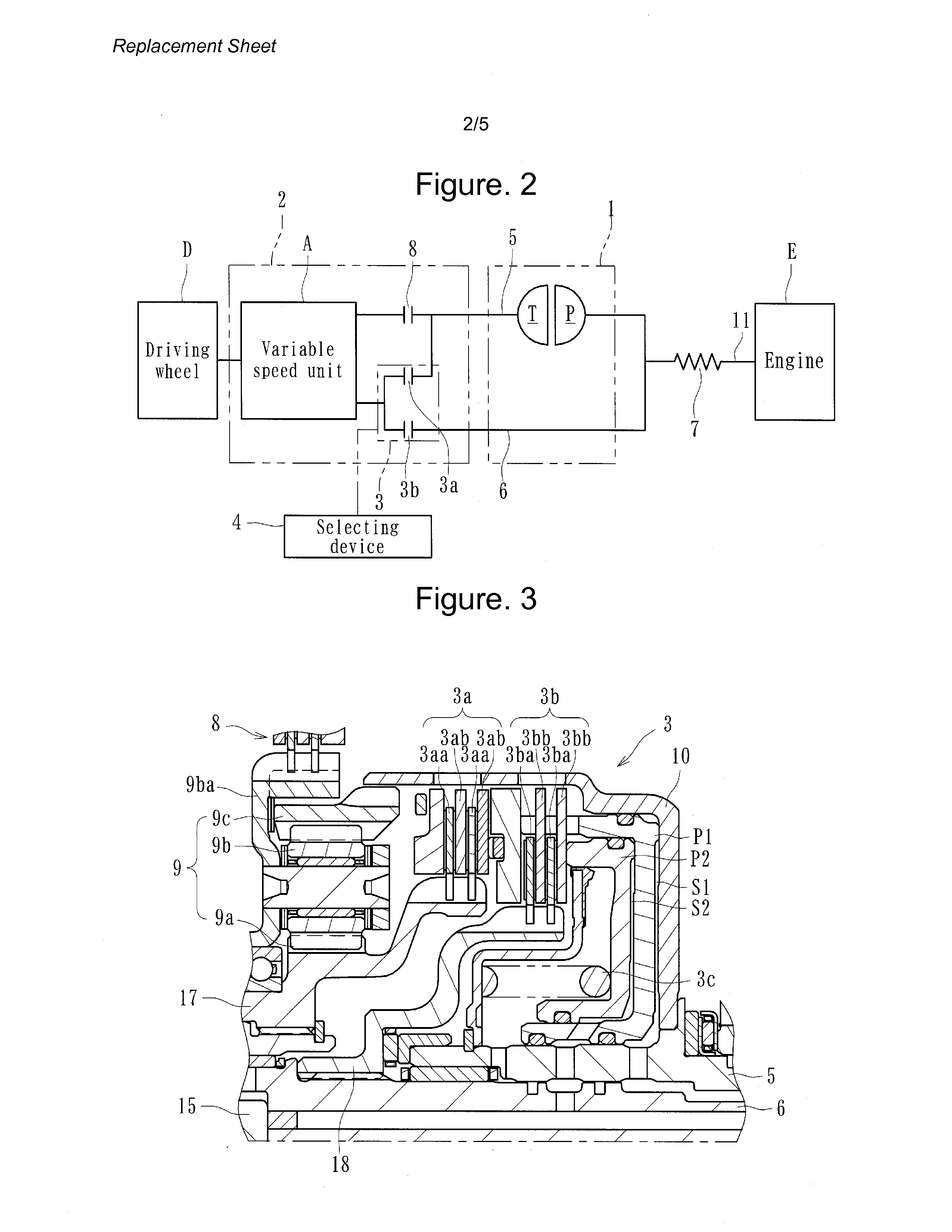
FIG. 1 illustrates a first embodiment of a power transmitting apparatus configured to transmit or cut off the driving force of an engine (driving source) of an automobile (vehicle) to a driving wheel (or driving wheels) D. Such an apparatus can comprise, as illustrated in FIGS. 1, 2 and 5, a torque converter 1, a clutch mechanism 3, a selecting device 4, a first driving shaft 5, a second driving shaft 6, a damper mechanism 7, and a third clutch device 8. FIG. 1 is a longitudinal-section view illustrating a main part of the power transmitting apparatus, and FIGS. 2 and 5 are schematic diagrams of the power transmitting apparatus of FIG. 1.

As illustrated in FIGS. 2 and 5, the torque converter 1 and a transmission 2 can be configured to perform as a power transmitting system that transmits power from the engine E as the driving source of a vehicle to the wheels D. The transmission 2 can include the clutch mechanism 3, the third clutch device 8 and a variable speed unit A. As illustrate...


PUM


Abstract

A power transmitting apparatus, such as an automotive transmission, can be configured to reduce the size of a torque converter as well as improve the flexibility of the torque converter's layout. A power transmitting apparatus configured to transmit power from a driving source of a vehicle to its wheels and can be configured selectively transmit or cutting-off the driving force to the wheels can comprise a torque converter having a torque amplifying function. A clutch mechanism can include a first clutch device to transmit the driving force to the wheels through a power transmitting system of the torque converter and a second clutch to transmit the driving force without the power transmitting system of the torque converter. A selecting device can control the first clutch device or the second clutch device in accordance with conditions of the vehicle including start of a vehicle from a stop. A damping mechanism for damping torque variation can be configured to transmit power between the driving source and the torque converter.

Description

CROSS-REFERENCE TO RELATED APPLICATIONSThis application is a continuation of PCT Application No. PCT / JP2009 / 006860, filed on Dec. 14, 2009, which claims priority to Japanese Application No. 2008-318379, filed on Dec. 15, 2008, the entire contents of each of which are hereby incorporated by reference.BACKGROUND OF THE DISCLOSURE1. Field of the DisclosureThe present inventions relate to power transmitting apparatuses, such as vehicle transmissions, which transmit power from a driving source of a vehicle to the wheels of the vehicle and which are adapted to properly select transmission of power and cutting-off of power to the wheels.2. Description of the Related ArtTwo types of known power transmitting apparatuses for vehicles (e.g., “automatic transmissions”) provide starting power (power for initiating movement of the vehicle from a stop) in different ways. One type uses a torque converter (“torque converter type”) and another type uses a starting clutch (“starting clutch type”) to p...

Claims


Application Information

Patent Timeline
Patent Type & Authority Applications(United States)
IPC IPC(8): F16D33/18
CPCF16D25/0638F16D25/10F16D2021/0661F16D2048/0212F16H37/027Y10T74/19037F16H47/085F16H2045/005F16H2045/0226F16H2045/0252F16H45/02F16D21/06
Inventor OHASHI, TATSUYUKIASATSUKE, SHOUJISUMI, MAKOTOOISHI, AKIOISHIKAWA, KEIICHI
Owner FCC KK
Why Eureka
Try Eureka