Whirlwind tank

A swirling pool and cone technology, applied in the direction of settlement tanks, etc., can solve the problems of increased concrete volume, increased structural weight, and increased project cost, and achieve the goal of improving the stress situation, increasing the working space, and increasing the space. Effect

Inactive Publication Date: 2010-02-10
CISDI ENG CO LTD
View PDF0 Cites 2 Cited by
  • Summary
  • Abstract
  • Description
  • Claims
  • Application Information

AI Technical Summary

Problems solved by technology

Increasing the weight of the structure itself includes increasing the thickness of the bottom plate, inclined cone, outer cylinder, and inner cylinder, which will increase the volume of concrete and increase the cost of the project
Utilizing the anti-floating ability of the foundation pit support structure includes improving the embedded capacity of the underground diaphragm wall or peripheral support piles, which is not suitable for the swirling pool structure without foundation pit support system

Method used


Image

  • Whirlwind tank
  • Whirlwind tank

Examples


Embodiment 1

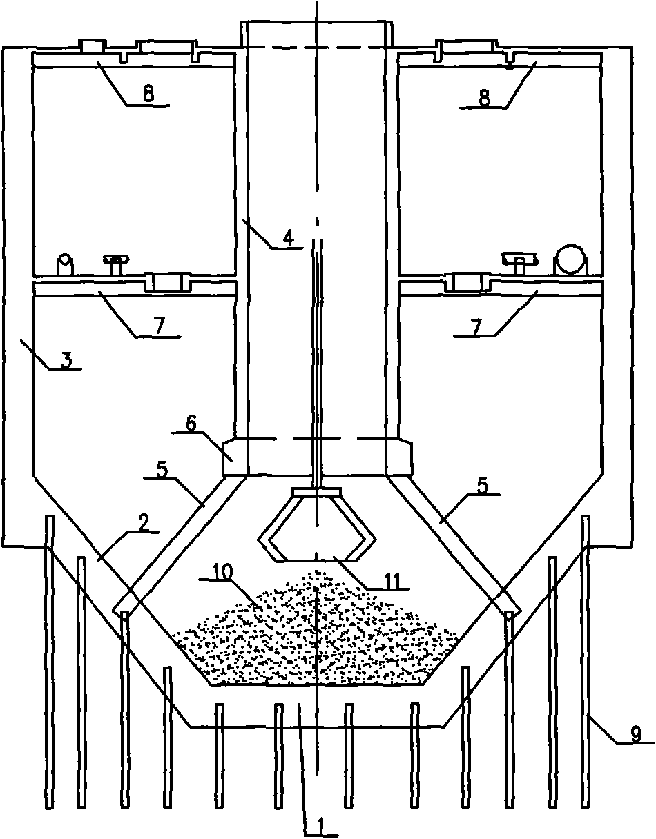
[0025] Embodiment 1: as figure 1 As shown, a swirl pool includes a bottom plate 1, an oblique cone 2, an outer cylinder 3, an inner cylinder 4, and eight oblique pillars 5 arranged in the circumferential direction; a reinforcing ring beam 6 is added to the bottom of the inner cylinder 4 The upper end of the pillar 5 is connected to the inner cylinder 4 through the reinforcing ring beam 6, and the lower end is connected to the inclined cone 2; the included angle between the inclined pillar 5 and the inner surface of the inclined cone 2 is 80°; the lower part of the inclined cone 2 and the bottom plate 1 is provided with anchor rod groups 9; the anchor rod groups 9 are manufactured by high-pressure grouting process.

[0026] When the swirl pool is working, iron slag 10 is accumulated on the bottom plate 1 and the inclined cone 2, and the grab bucket 11 grabs the iron slag in the space surrounded by the inclined pillars 5. The buoyancy is balanced by the pull-out force of the an...

Embodiment 2

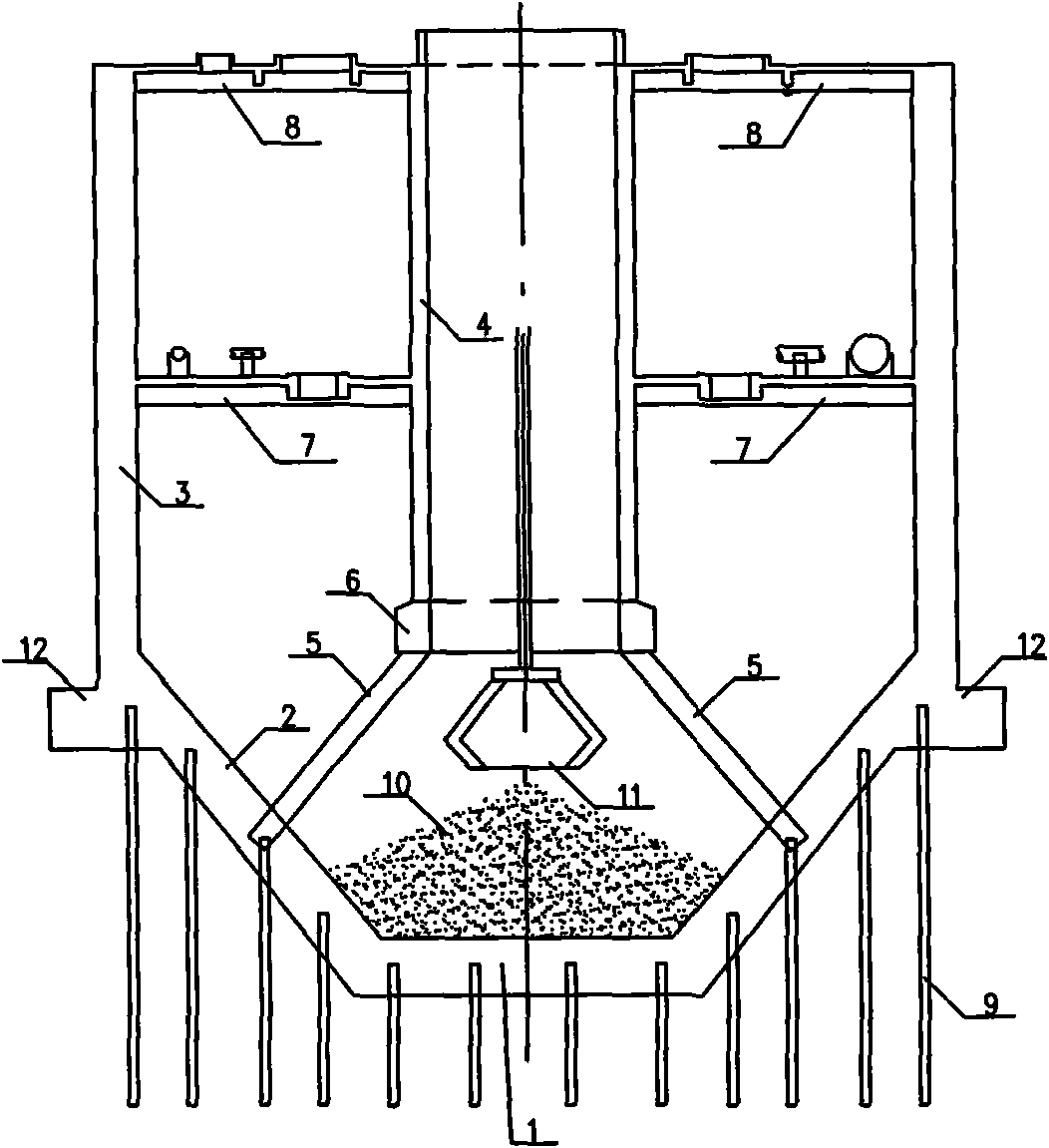
[0027] Embodiment 2: as figure 2 As shown, the difference between this embodiment and Embodiment 1 is that an external protruding ring beam 12 is provided at the junction of the oblique cone 2 and the outer cylinder 3 . Other structures of this embodiment are the same as those of Embodiment 1. When the swirl pool of this embodiment is in operation, the earth pressure acts vertically on the lower surface of the inclined cone 2 and the bottom plate 1, and the outer hanging ring beam 12 constrains the top of the inclined cone 2, and the top of the inclined cone 2 generates an outward thrust, and the outer hanging The ring beam 12 is under tension; on the other hand, the earth pressure acts vertically on the outer surface of the outer cylinder 3, the overhanging ring beam 12 constrains the bottom of the outer cylinder 3, and the overhanging ring beam 1 is under compression, which can partially balance the top of the inclined cone 2 outward thrust. The other components of this e...


PUM


Abstract

The invention relates to a whirlwind tank, comprising a bottom plate (1), an oblique cone (2), an outer barrel (3), an inner barrel (4) and a support (5), wherein the support (5) is an oblique support. The whirlwind tank causes grab bucket working performance to be high, and floating resistant capability of the whirlwind tank is strong.

Description

technical field [0001] The invention relates to a structural system of a swirl pool, which belongs to the technical field of structural engineering mainly constructed of concrete. Background technique [0002] The swirling pool is a circular underground cavity structure, and its technological feature is to remove iron slag in the water body through swirling sedimentation. The water body carrying iron slag rotates downward along the tangent of the inner cylinder and enters the inner cylinder. The iron slag rotates and settles on the bottom plate. The grab bucket grabs the iron slag and transports it away. The water flows through the pillar and is pumped away for the next step of treatment. At present, the conventional practice is that the pillar stands vertically on the bottom plate to support the inner cylinder. This method is not conducive to grabbing the iron slag when the grab bucket is opened, and the iron slag can only be deposited in the inner cylinder range, and the ...

Claims


Application Information

Patent Timeline
Patent Type & Authority Applications(China)
IPC IPC(8): B01D21/02
Inventor 邓玉孙蒙瑜林红薛尚铃
Owner CISDI ENG CO LTD
Why Eureka
Try Eureka