
Radial jet air impingement nozzle, oven and method

a technology of air impingement nozzle and radial jet, which is applied in the direction of baking, household heating details, containers, etc., can solve the problems of overcooked and undercooked areas of food products, and achieve the effects of high heat distribution cooking, enhanced heat transfer to the product, and more homogeneous

Inactive Publication Date: 2011-06-02
MANITOWOC FOODSERVICE UK
View PDF9 Cites 11 Cited by
  • Summary
  • Abstract
  • Description
  • Claims
  • Application Information

AI Technical Summary

Benefits of technology

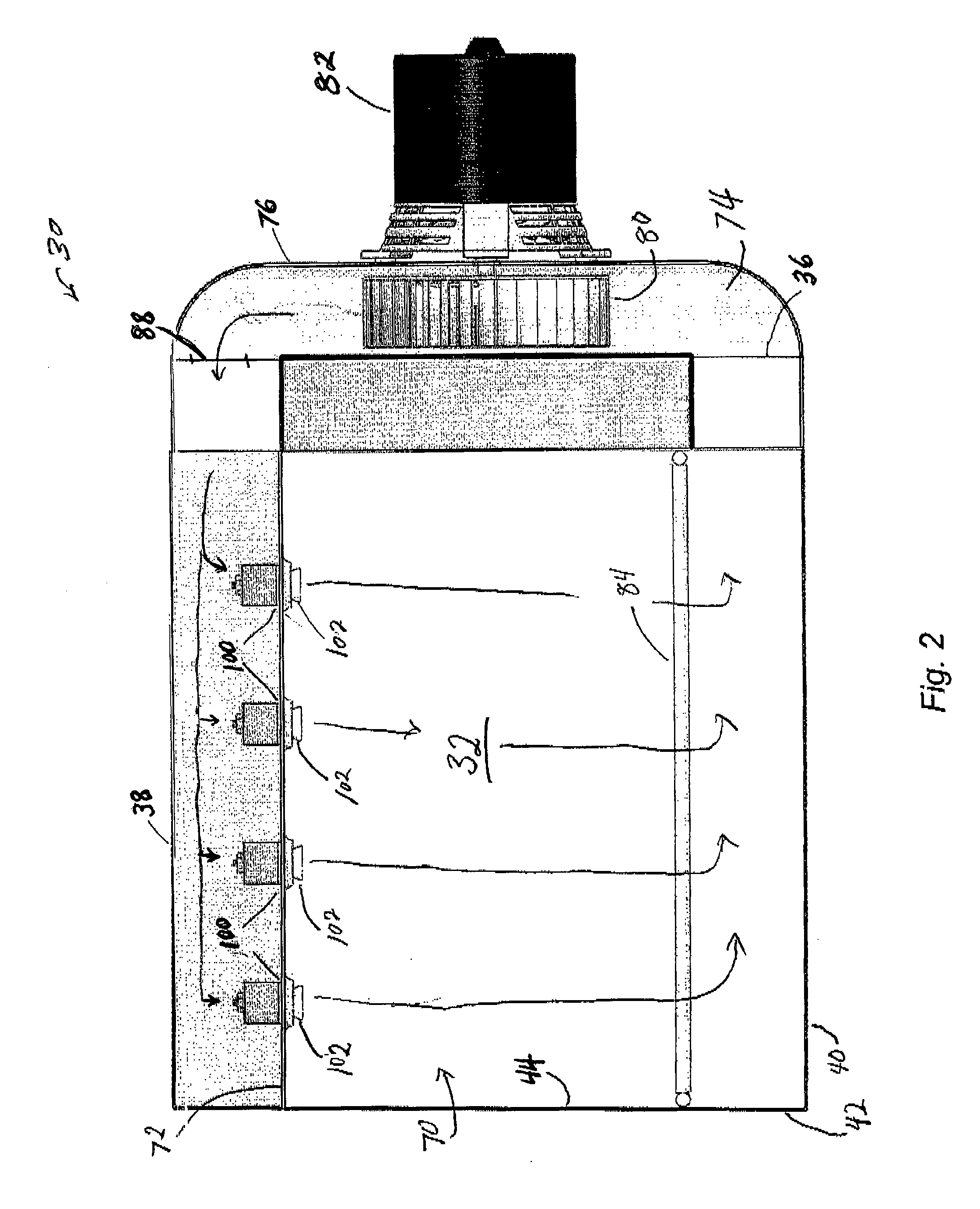
[0006]The present disclosure describes a jet nozzle that provides hot air acceleration and a nozzle insert or member in the flow path beneath the jet nozzle that transforms the air flow to create a relatively thin thermal boundary layer of hot air at the surface of the food, utensil or any other material placed within the air stream that is characterized by an overall flow pattern at the surface of the food product that enhances the heat transfer to the product. In a preferred embodiment, the member has a cone like or goblet like shape that causes the airflow to form a relatively thin bell-shaped flow ring after separating from the nozzle insert, which leads to a more homogeneous and high heat distribution cooking of food products.
[0010]In another embodiment of the oven of the present disclosure, the slot-shaped orifice has a thickness that produces an overall flow pattern at the surface of the product that enhances heat transfer to the product and a homogeneous heat transfer at a surface of the product.
[0013]In another embodiment of the oven of the present disclosure, the jet nozzle is one of a plurality of jet nozzles that each have an associated nozzle insert in relation to the jet nozzle to form about the nozzle insert a slot-shaped orifice through which the impingement air flows. The plurality of jet nozzles collectively provide a homogeneous and high heat transfer distribution at the product.
[0026]In another embodiment of the method of the present disclosure, the slot-shaped orifice has a thickness that produces an overall flow pattern at the surface of the product that enhances heat transfer to the product and a homogeneous heat transfer at a surface of the product.

Problems solved by technology

A disadvantage of these nozzles is that the columns of hot impingement air develop hot spots that result in a pattern of overcooked and undercooked areas of the food product.

Method used


Image

  • Radial jet air impingement nozzle, oven and method
  • Radial jet air impingement nozzle, oven and method
  • Radial jet air impingement nozzle, oven and method

Examples


Embodiment Construction

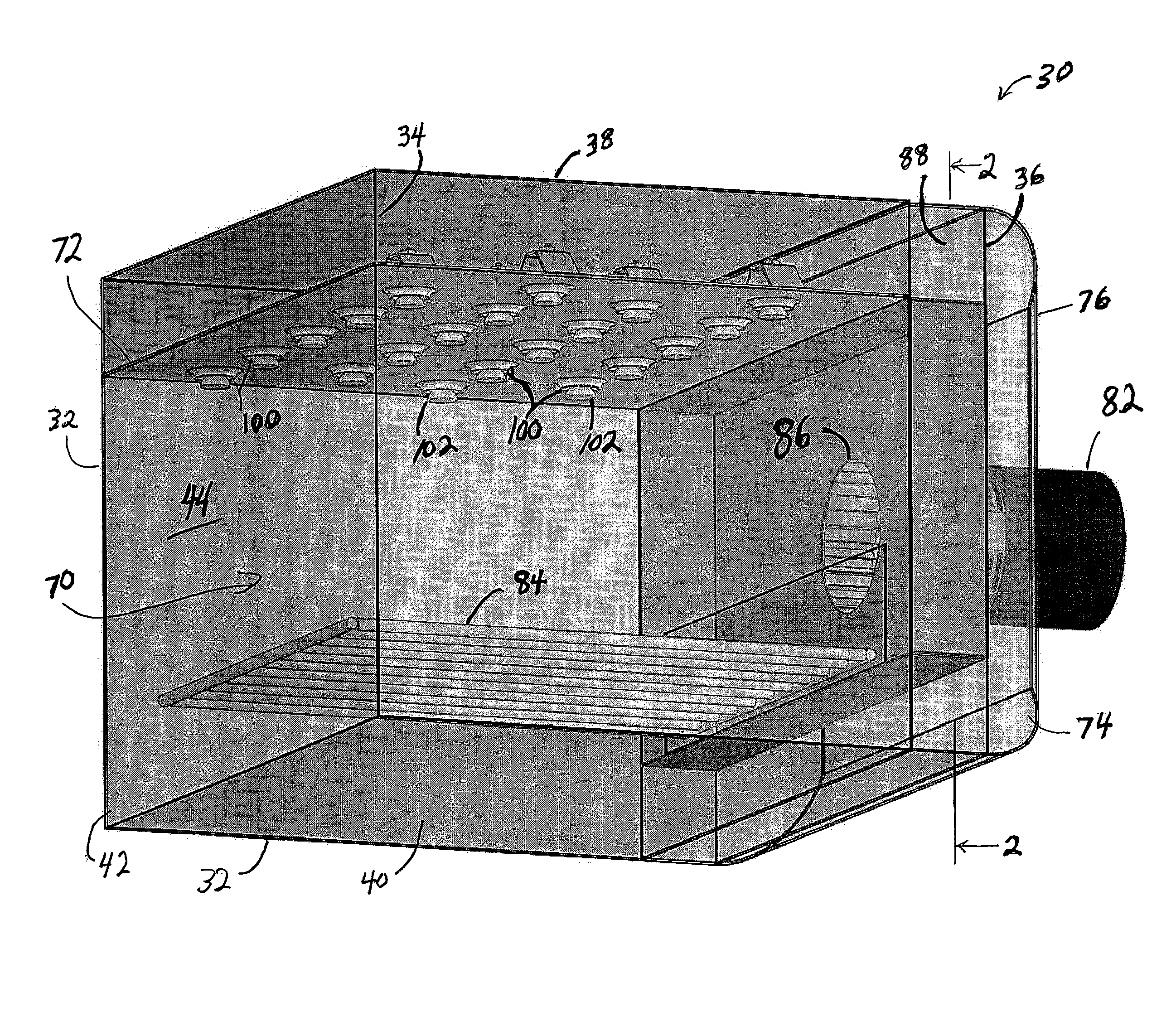
[0046]It is contemplated that the jet nozzles of the present disclosure can be used in any type of oven that uses impingement air. By way of example and completeness of description, the nozzles are described herein for use with a countertop oven.

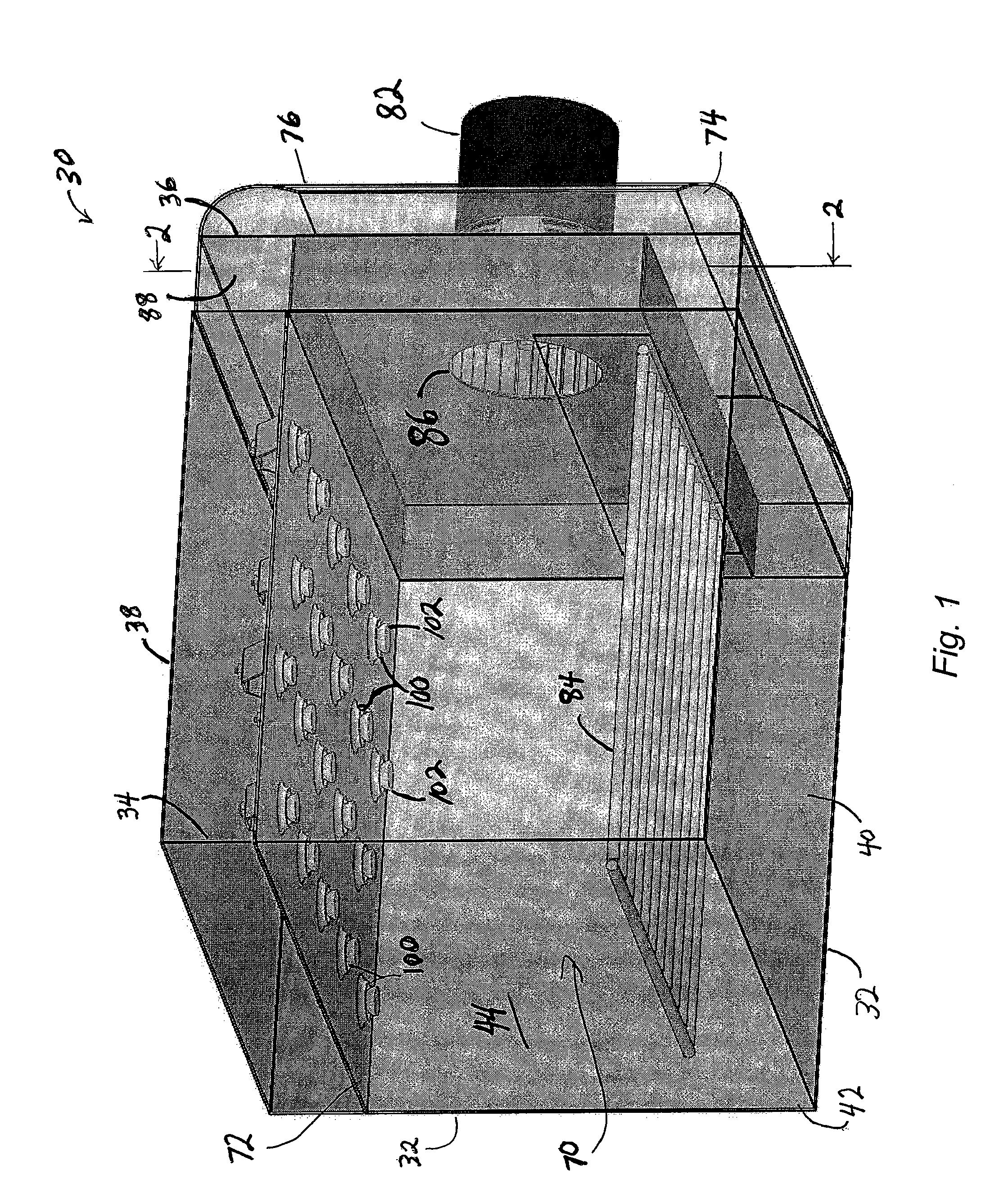
[0047]Referring to FIGS. 1 and 2, an oven 30 of the present disclosure comprises a pair of side walls 32 and 34, a back wall 36, a top wall 38, a bottom wall 40 and a front wall 42. Front wall 42 comprises a door 44 and a control panel 50 (shown in FIG. 3), which, for example, may be located above, below or beside door 44. A handle (not shown) is disposed on door 42 for opening the door in a pull down manner or a side rotatable manner.

[0048]Oven 30 comprises an oven chamber 70 defined by side walls 32 and 34, back wall 36, bottom wall 40 and a jet plate 72. Jet plate 72 is disposed below top wall 38. Oven 30 further comprises a fan box 74 defined by side walls 32 and 34, back wall 36, top wall 38 and a wall 76. A fan 80 is disposed in fan bo...


PUM


Abstract

An oven that generates impingement air with a jet nozzle that includes a nozzle insert that provides a slot-shaped orifice through which the air flows toward a product to be heated or cooled. In particular, an oven for cooking a food product is disclosed in which a plurality of the jet nozzles produces an overall turbulence and a homogeneous heat transfer at a surface of the food product.

Description

RELATED APPLICATION[0001]This application claims the benefit of U.S. Provisional Application Ser. No. 61 / 180,575, filed on May 22, 2009, the entire contents of which are incorporated herein.FIELD OF THE INVENTION[0002]This disclosure relates to new and improved air impingement nozzles, methods and ovens that use the nozzles for heating or cooling a product within the air streams coming out of the air impingement nozzles. For example, the improved impingement nozzles can be used in an oven for cooking food products.BACKGROUND OF THE DISCLOSURE[0003]Jet nozzles are used to provide impingement air to heat or cool a product in a variety of ovens, including countertop ovens, conveyor ovens, and the like. Several known jet nozzles are shown in U.S. Pat. No. 6,817,283, which discloses an oven for cooking food products. In some applications, the jet nozzles are shaped and spaced to provide non-overlapping columns of hot impingement air that impinge directly on the surface of the food produc...

Claims


Application Information

Patent Timeline
Patent Type & Authority Applications(United States)
IPC IPC(8): F24C15/32
CPCA21B1/245
Inventor BEHLE, MARTINJONES, DOUGLAS S.
Owner MANITOWOC FOODSERVICE UK
Learn More