
Microvalve and valve seat member

Inactive Publication Date: 2011-06-02
MURATA MFG CO LTD
View PDF24 Cites 7 Cited by
  • Summary
  • Abstract
  • Description
  • Claims
  • Application Information

AI Technical Summary

Benefits of technology

[0007]To overcome the problems described above, preferred embodiments of the present invention provide a microvalve in which a displacement member can open and close an opening of a valve housing with consistent sealing performance, and a valve seat member.

Problems solved by technology

In this type of fuel battery system, an unintended flow of fuel in the forward direction due to gravity can occur and unnecessary fuel can be supplied to the reacting furnace even when the pump is stopped.
This can lead to a surplus of electric power generation.
However, the check valves are valves for stopping a reverse flow and cannot block a forward flow.
In general, a valve seat member made of a soft material, such as rubber, is fixed to the opening since a sufficient seal is not produced by simply making the previously described valve body contact the opening of the valve housing directly.
However, when the intended fluid is an organic solvent, such as, for example, methanol, which is used as a fuel for fuel batteries, there is a possibility that the adhesive will be corroded, the fixing will become unstable, and the bond will peel off.
Furthermore, if the valve seat is fixed to the valve housing in a tilted state or in an off-center state, the valve seat and the valve body do not make proper contact and consistent sealing performance may not be obtained.

Method used


Image

  • Microvalve and valve seat member
  • Microvalve and valve seat member
  • Microvalve and valve seat member

Examples


first preferred embodiment

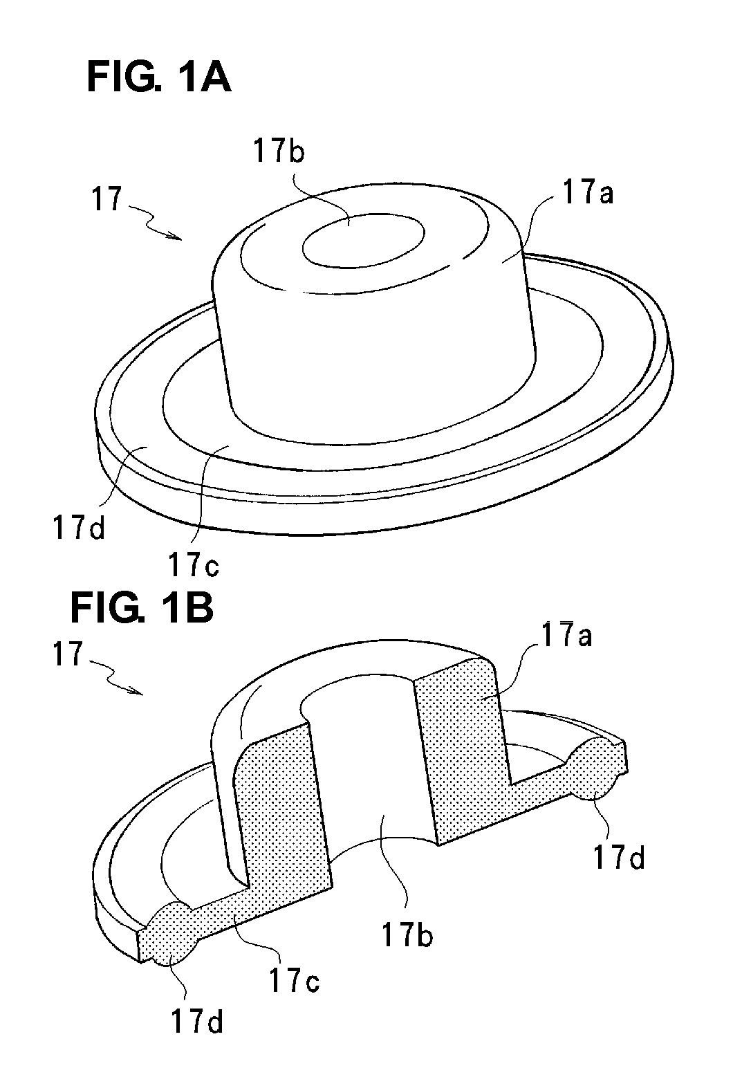
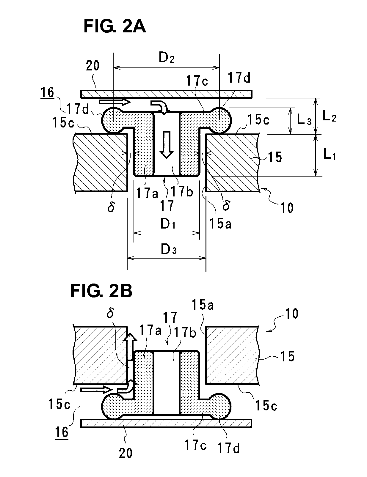
[0032]FIGS. 1 to 3 illustrate a valve seat member 17 according to a preferred embodiment of the present invention. As illustrated in FIG. 1, the valve seat member 17 preferably integrally includes a cylinder portion 17a that includes a through hole 17b in a central portion thereof, a flange portion 17c that has a circumference greater than that the cylinder portion 17a and is provided at an axial end of the cylinder portion 17a. An annular seal portion 17d that is thicker than the flange portion 17c is preferably provided around the periphery of the flange portion 17c. The valve seat member 17 is preferably integrally made from a rubber material such as fluorine, silicone, or EPDM, for example. The cylinder portion 17a is preferably arranged in an opening 15a of a top plate 15 of a valve housing 10, and the seal portion 17d contacts the top surface of the top plate 15 (seal surface 15c). The seal portion 17d according to the first preferred embodiment is preferably annular and has a...

second preferred embodiment

[0038]FIG. 4 to FIG. 9 show a preferred embodiment of a microvalve that uses the valve seat member 17 described above. A microvalve A according to the present preferred embodiment is preferably used as an active valve to control the flow of fluids, such as methanol, for example. The microvalve A preferably includes a box-shaped valve housing 10 preferably made of a hard material, such as metal or resin, for example, and a rectangular or substantially plate-shaped actuator 20. As shown in FIG. 5, the valve housing 10 is preferably a lamination of a rectangular or substantially rectangular plate-shaped bottom plate 11 that is wider than the actuator 20, a rectangular plate-shaped first frame 12 disposed on the upper surface of the bottom plate 11 and with an inside width wider than the actuator 20, a pair of U-shaped press plates 13 disposed on the upper surfaces of both longitudinal sides of the first frame 12 and having a thickness approximately the same as the thickness of the actu...

third preferred embodiment

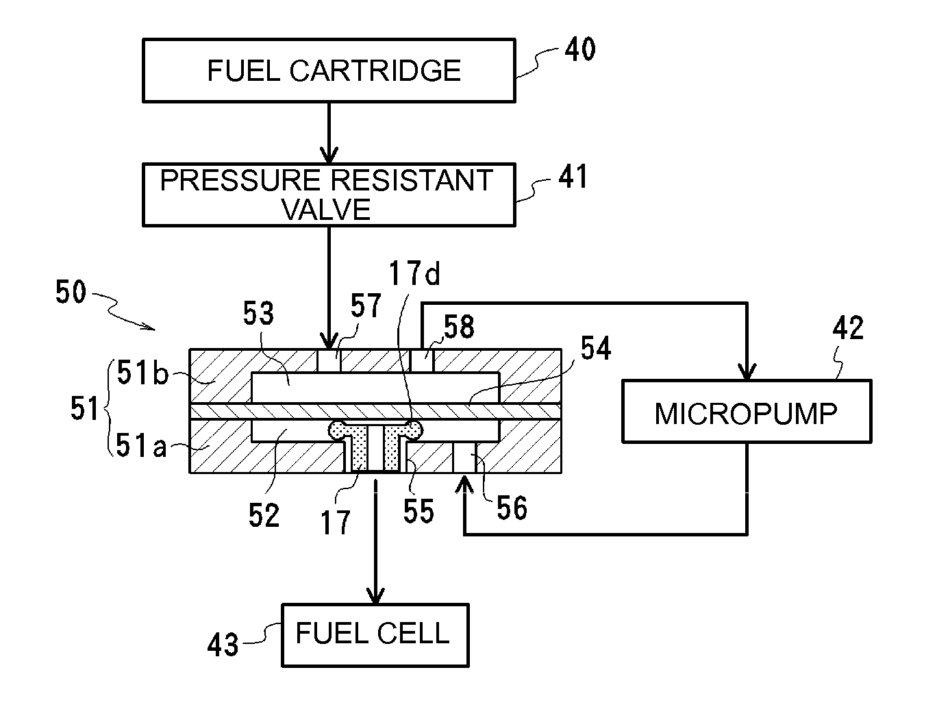
[0046]FIG. 10 shows a microvalve according to another preferred embodiment of the present invention that is used in fuel cell supply device. The supply device preferably includes a fuel cartridge 40, a pressure resistant valve 41, a micropump 42, and a microvalve 50. The fuel, for example, methanol, included in the fuel cartridge 40 is supplied from the microvalve 50 via the pressure resistant valve 41 and the micropump 42 to a fuel cell 43.

[0047]The microvalve 50 is an example of a passive valve that opens according to the motions of the micropump 42, and preferably includes a valve housing 51 including two upper and lower cases 51a and 51b, and a diaphragm 54 sandwiched between the cases 51a and 51b and dividing the value housing 51 into a first valve chamber 52 and a second valve chamber 53. The valve housing 51 is preferably made of a hard material, such as metal or resin, for example, and the diaphragm 54 is preferably made of a thin resin plate or metal plate, for example. A f...


PUM


Abstract

In a microvalve, a valve seat includes a cylinder portion that includes a through hole in a central portion thereof, and a flange portion that is provided around an axial end of the cylinder portion and that has a thick seal portion on a periphery of the flange portion. The cylinder portion is disposed in an opening of a valve housing with a gap δ therebetween, and the seal portion is able to move away from the seal surface provided around the opening and away from the displacement member. In an open state, at least one of a flow path through the through hole and a flow path through the gap between the cylinder portion and the opening is open, and in a closed state, the seal portion is sandwiched between the displacement member and the seal surface.

Description

BACKGROUND OF THE INVENTION[0001]1. Field of the Invention[0002]The present invention relates to a microvalve, and in particular, to a valve that opens and closes an opening through a displacement member, and also relates to a valve seat member included in the valve.[0003]2. Description of the Related Art[0004]Generally, items such as mobile personal computers that include fuel batteries for electrical power are being developed. Liquid fuels, such as methanol and ethanol, are used as fuel, and by supplying the fuel to a reacting furnace via a micropump, the reacting furnace causes the fuel and air to react to generate electrical power. In this type of fuel battery system, an unintended flow of fuel in the forward direction due to gravity can occur and unnecessary fuel can be supplied to the reacting furnace even when the pump is stopped. This can lead to a surplus of electric power generation. Micropumps are equipped with check valves. However, the check valves are valves for stoppi...

Claims


Application Information

Patent Timeline
IPC IPC(8): F16K1/00
CPCF16K99/0048F16K99/0015
Inventor TAKAHASHI, YUKIKOTANI, KENICHI
Owner MURATA MFG CO LTD
Learn More