

Random number generation system with ring oscillators
a random number and ring oscillator technology, applied in pulse generators, pulse techniques, instruments, etc., can solve the problems of introducing a significant latency for the buffer to be filled, and the cost of a large secure buffer is typically high
- Summary
- Abstract
- Description
- Claims
- Application Information
AI Technical Summary
Benefits of technology
Problems solved by technology
Method used
Image

Examples
Embodiment Construction
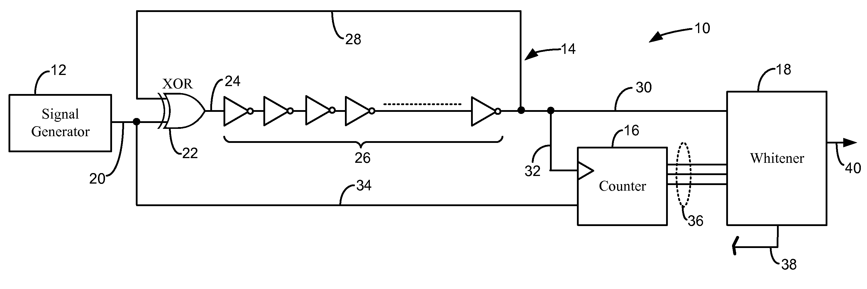
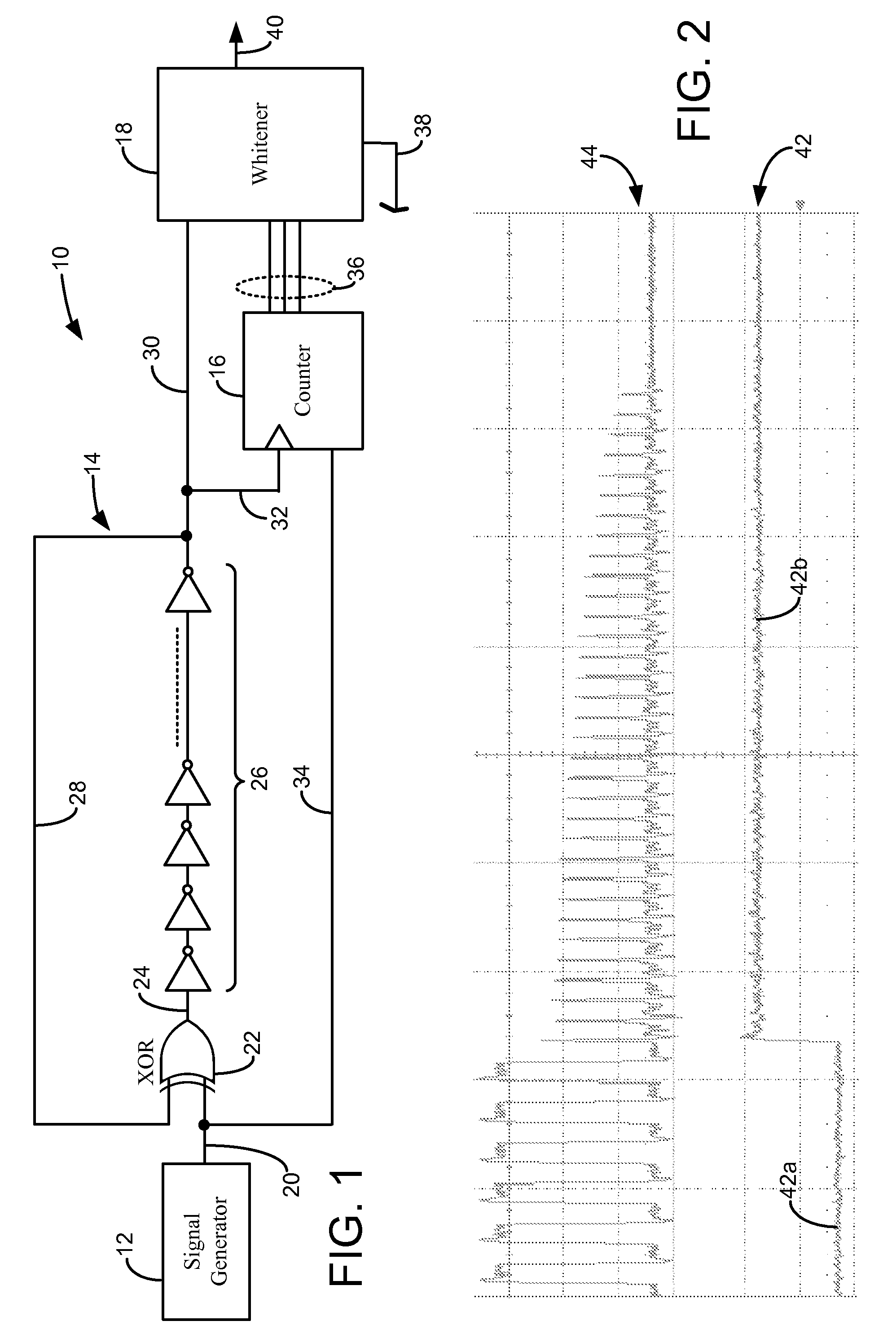
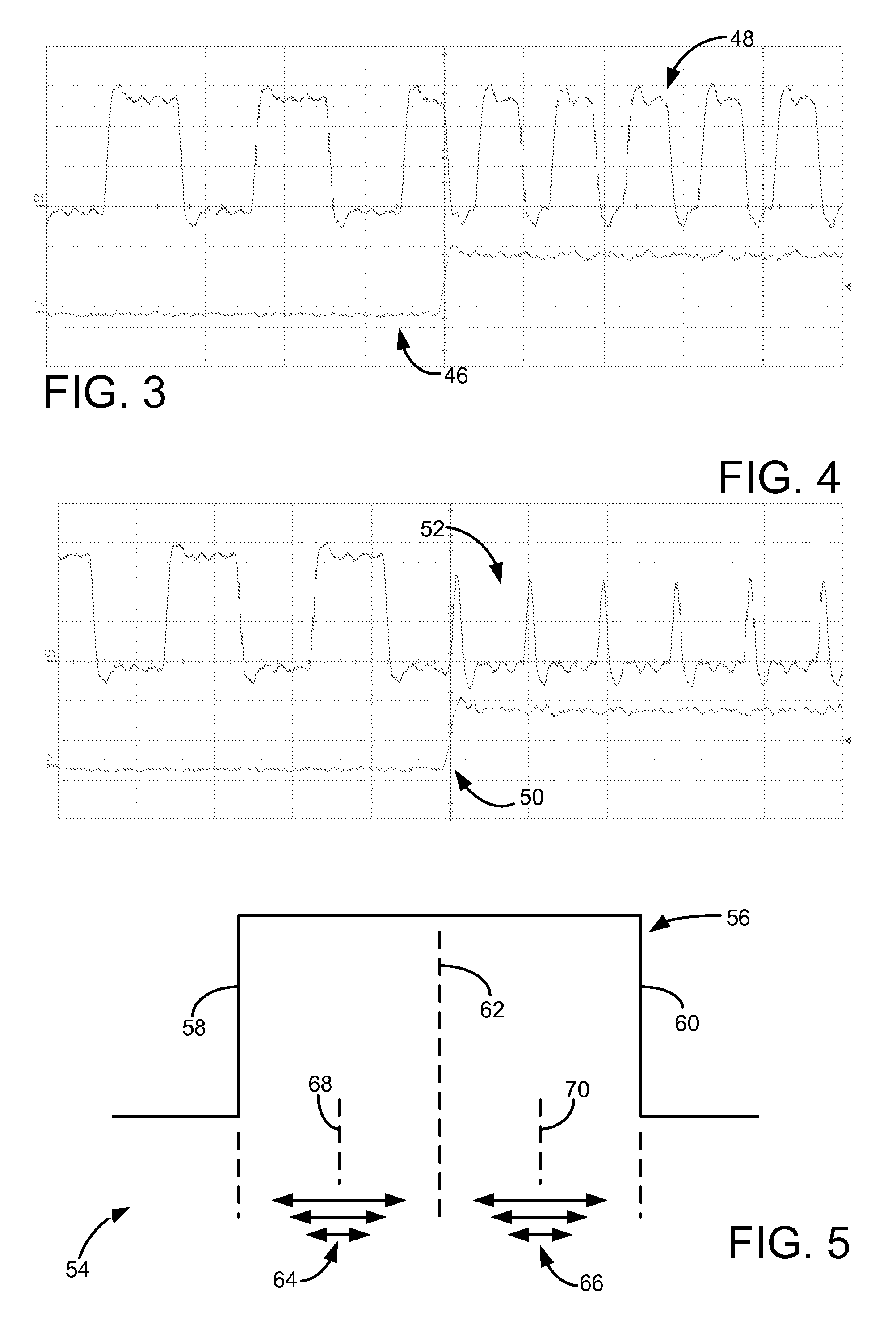
[0019]The present disclosure is directed to systems and processes for generating random numbers with the use of one or more ring oscillators. In one aspect (shown in FIGS. 1-8), the ring oscillator(s) are each configured to switch between a first state (referred to an oscillating state) and a second state (referred to as a latched state). While in the oscillating state, the ring oscillator generates an output signal that oscillates between logic levels “0” and “1”. Over successive cycles through the ring oscillator, the oscillating output signal desirably accumulates random phase drift due to noise from internal and external system sources.
[0020]When switched to the latched state, the ring oscillator may function as a latch circuit, thereby allowing the oscillating output signal to settle to a logic level. As discussed below, the time required for the output signal to settle to a logic level is dependent on the edge locations of the output signal relative to edge locations of a cont...
PUM
 Abstract
Description
Claims
Application Information