Liquid ejecting apparatus

a liquid ejecting and ejector technology, applied in the direction of printing, other printing apparatus, etc., can solve the problems of uneven recording quality, clogging of recording heads, and non-uniform concentration of solid content in ink

Active Publication Date: 2011-06-02
SEIKO EPSON CORP
View PDF12 Cites 4 Cited by
  • Summary
  • Abstract
  • Description
  • Claims
  • Application Information

AI Technical Summary

Benefits of technology

[0022]With this configuration, liquid can be preferentially supplied to the liquid ejecting head from the tank of which residual amount of liquid is larger. Accordingly, liquid droplets can be discharged from the liquid ejecting head stably for a long period of time.

Problems solved by technology

This causes non-uniformity of solid content concentration in the ink.
Therefore, there arise disadvantages that nozzle clogging of the recording head is caused and further unevenness of recording quality is caused.
However, if it is assumed that the residual amount of ink in the main tank is 10 ml and the residual amount of ink in the sub tank is 90 ml, even if ink is flown into the sub tank from the main tank by 10 ml when the power is turned ON, a sufficient stirring effect cannot be obtained in the sub tank.

Method used


Image

  • Liquid ejecting apparatus
  • Liquid ejecting apparatus
  • Liquid ejecting apparatus

Examples


Embodiment Construction

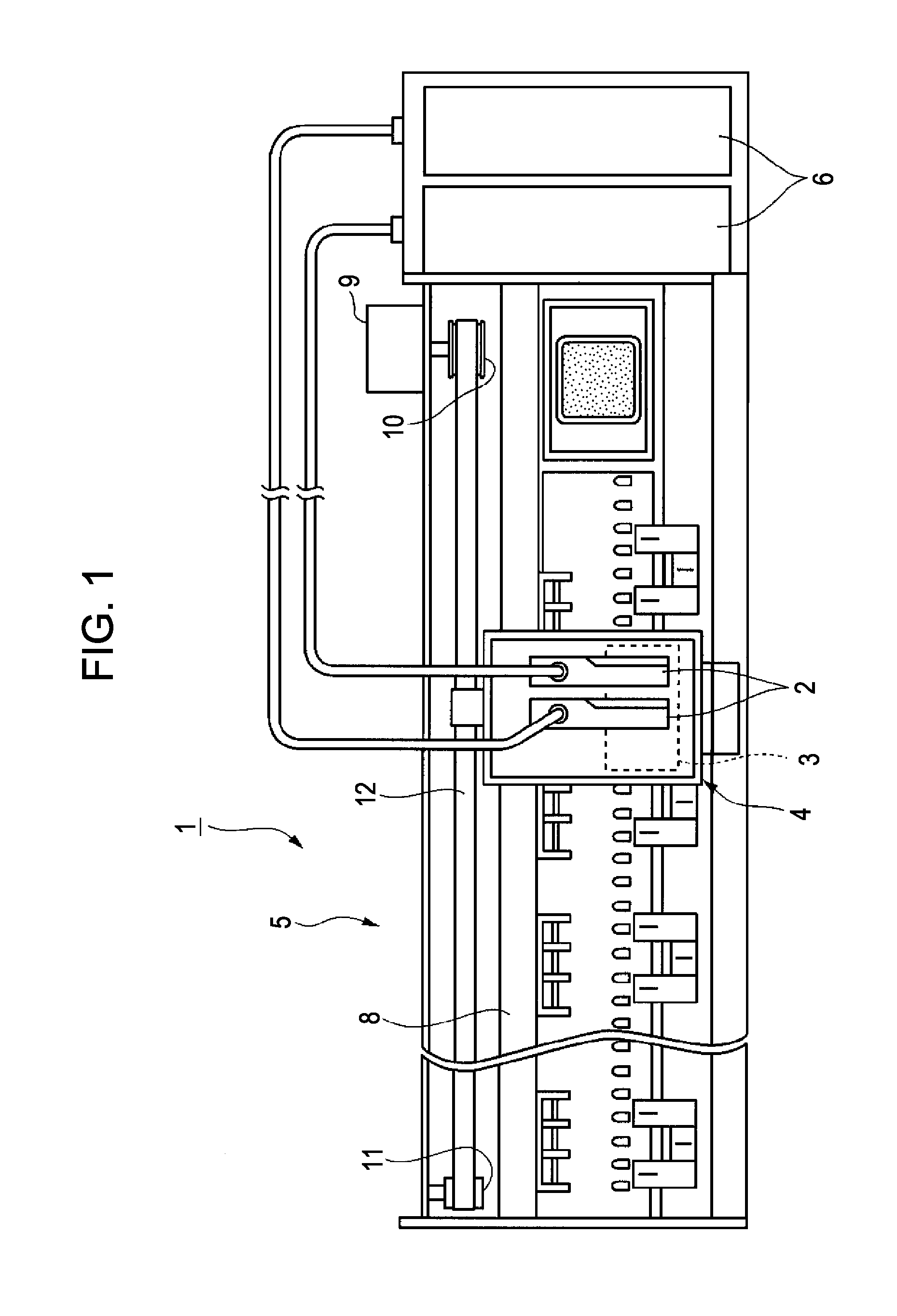
[0029]Hereinafter, an embodiment of the invention is described with reference to drawings. FIG. 1 is a fragmentary exploded view illustrating a schematic configuration of a printer (liquid ejecting apparatus) according to an embodiment of the invention. In FIG. 1, a reference numeral 1 denotes the printer.

[0030]The printer 1 is schematically configured to include a carriage 4 on which a sub tank (first tank) 2 and a recording head (liquid ejecting head) 3 are mounted, a printer main body 5, and a main tank (second tank) 6 formed by an ink cartridge.

[0031]The printer main body 5 is provided with a carriage movement mechanism (not shown), a paper feeding mechanism (not shown) and the main tank 6 (ink cartridge). The carriage movement mechanism reciprocates the carriage 4. The paper feeding mechanism transports a recording paper (not shown). The main tank 6 stores (accommodates) ink to be supplied to the recording head 3.

[0032]The carriage movement mechanism includes a guiding shaft 8,...


PUM


Abstract

In a liquid ejecting apparatus, when a ON/OFF detector detects that power of the liquid ejecting apparatus is switched to an ON state from an OFF state, a controller controls a liquid transfer unit such that liquid is transferred to a tank of which residual amount of liquid is smaller from a tank of which residual amount of liquid is larger based on the residual amount of liquid in a first tank detected by the first liquid residual amount detector and the residual amount of liquid in a second tank detected by the second liquid residual amount detector.

Description

BACKGROUND[0001]1. Technical Field[0002]The present invention relates to a liquid ejecting apparatus.[0003]2. Related Art[0004]As a liquid ejecting apparatus, an ink jet printer (hereinafter, referred to as printer) which ejects ink (liquid) onto a recording medium from ejection orifices (nozzles) of a recording head (liquid ejecting head) has been known.[0005]The printer includes a tank which accommodates ink. In the printer, ink in the tank is supplied to a recording head and ink is discharged from the recording head. The ink is commonly made of a dispersion containing solid content such as pigment and a dispersion medium such as a solvent.[0006]When such ink is used in the printer, particularly if the printer is made to be in an OFF state and is kept to be in a non-used state for a long period of time, the solid content in the ink accommodated in the tank is separated and settled down (precipitated). This causes non-uniformity of solid content concentration in the ink. Then, if t...

Claims


Application Information

Patent Timeline
Patent Type & Authority Applications(United States)
IPC IPC(8): B41J29/38
CPCB41J29/393B41J2/17509
Inventor AKATSUKA, YASUSHITAKAHASHI, NOBUHITO
Owner SEIKO EPSON CORP
Why Eureka
Try Eureka