Laser beam source device, projector, and monitoring device
- Summary
- Abstract
- Description
- Claims
- Application Information
AI Technical Summary
Benefits of technology
Problems solved by technology
Method used
Image

Examples
Example
First Embodiment
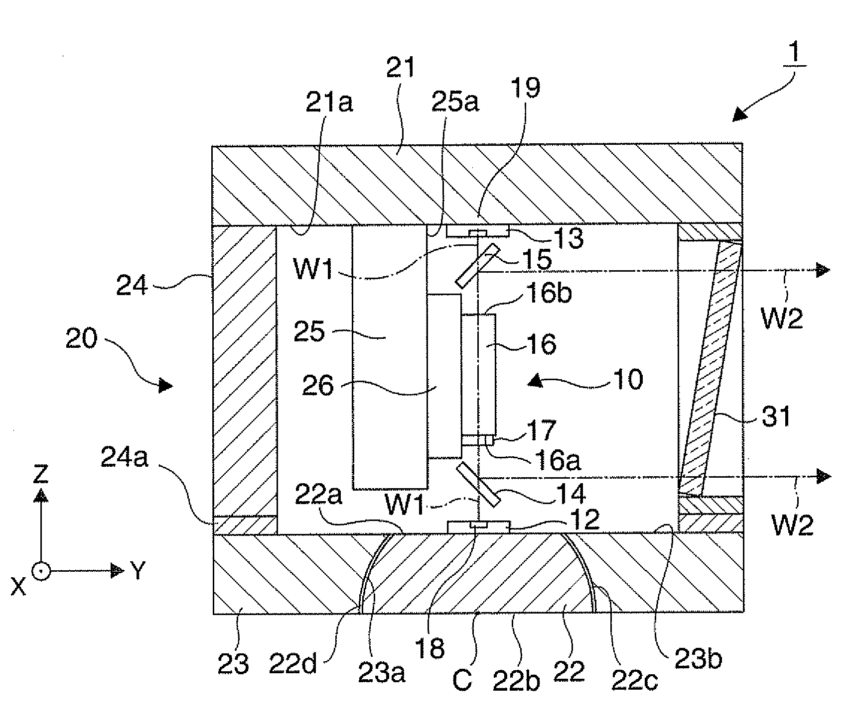
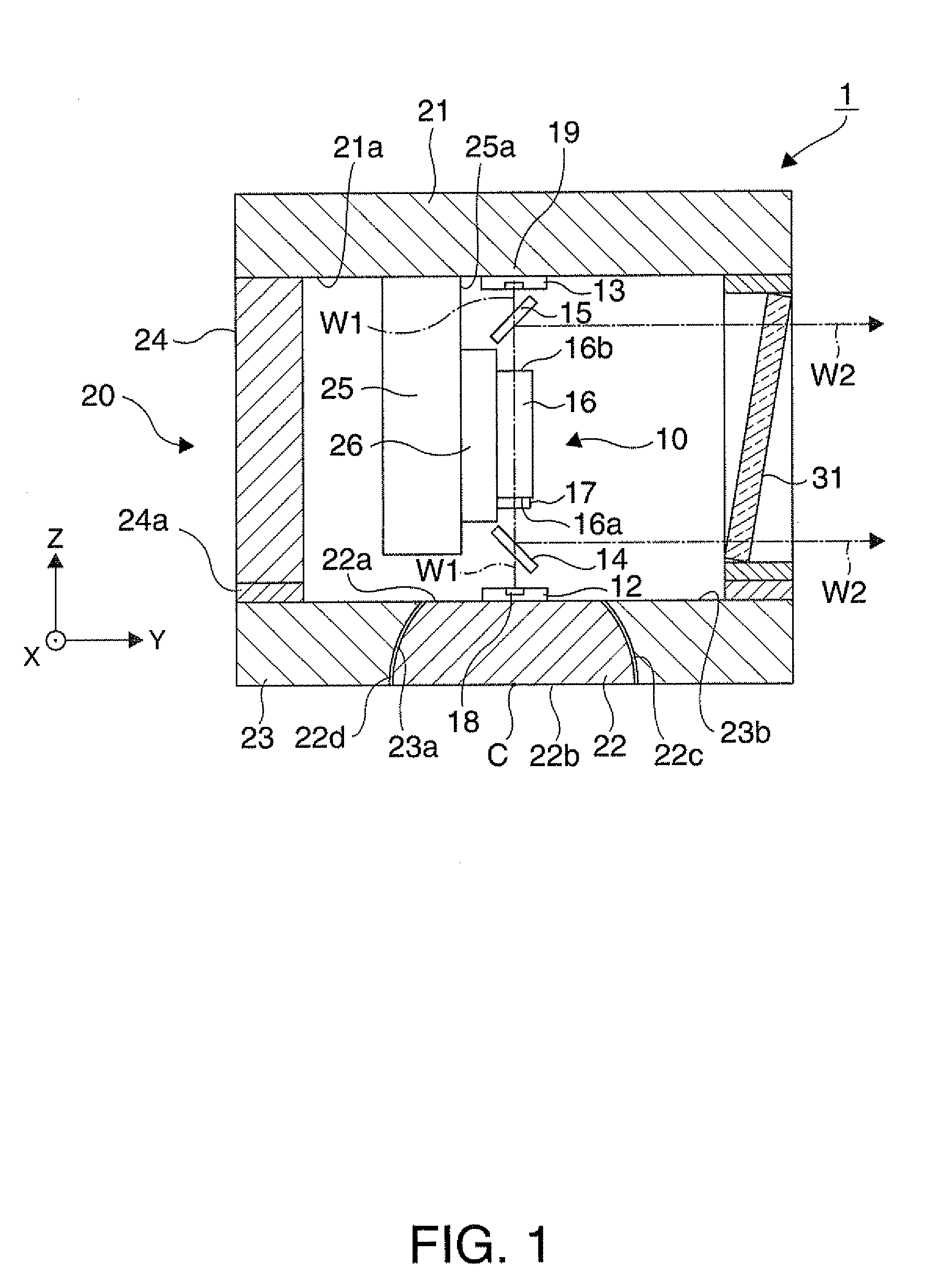
[0036]As illustrated in FIG. 1, a laser beam source device 1 includes an optical system 10 and a holding unit 20.
[0037]The optical system 10 has a first semiconductor laser element (first light emission element) 12, a second semiconductor laser element (second light emission element) 13, a first dichroic mirror (dividing unit: first dividing unit) 14, a second dichroic mirror (dividing unit: second dividing unit) 15, a wavelength converting element 16, and a BPF (wavelength selecting element) 17.
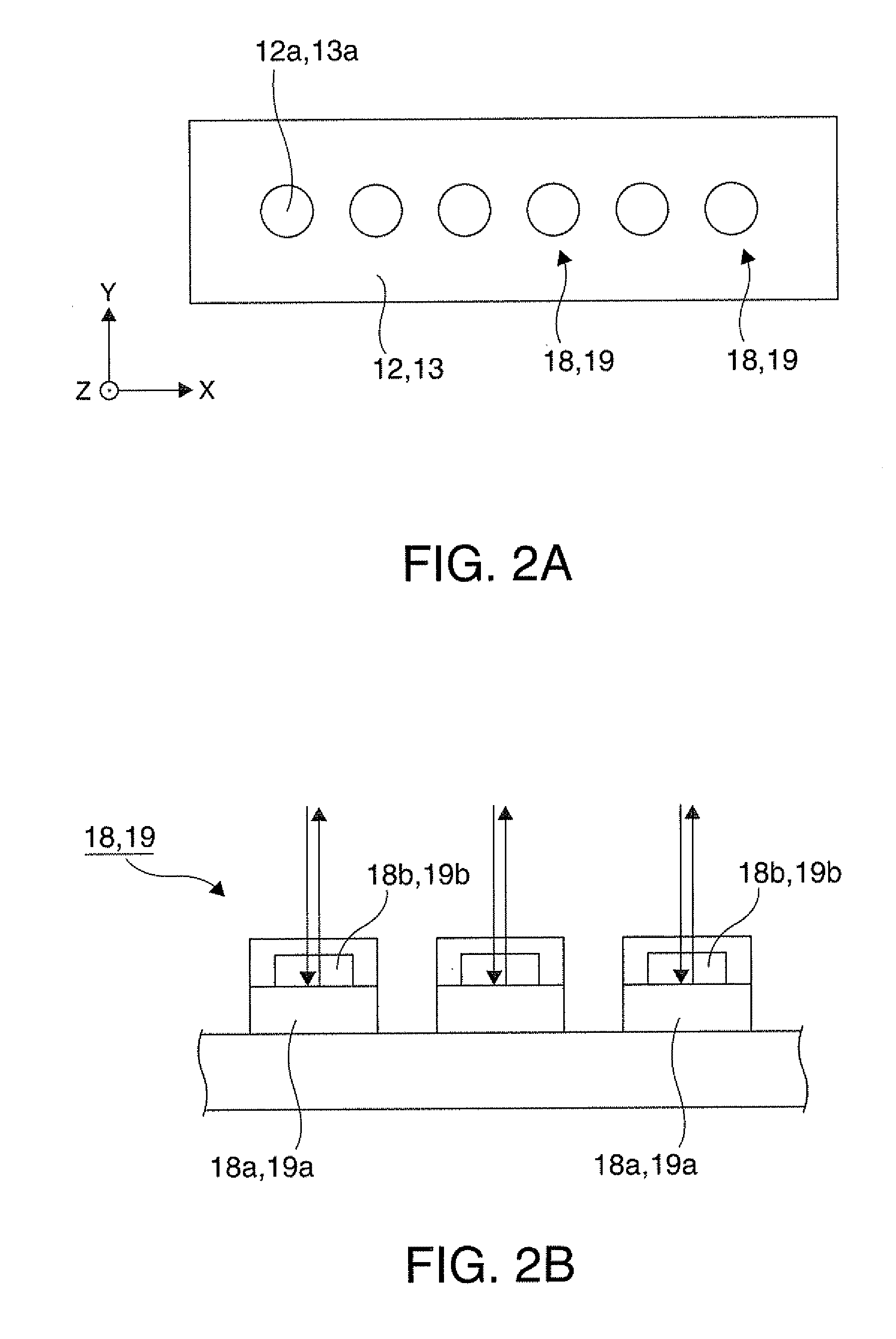
[0038]The emission directions of laser beams emitted from the first and second semiconductor laser elements 12 and 13 correspond to a Z axis direction, the arrangement directions of emitters 18 and 19 described later correspond to an X axis direction, and the axis crossing the emission directions and the arrangement directions at right angles corresponds to a Y axis direction.
[0039]As illustrated in FIG. 2A, each of the first and second semiconductor laser elements 12 and 13 ...
Example
Second Embodiment
[0066]A second embodiment according to the invention is now described with reference to FIG. 4. In the figures associated with the respective embodiments, the same reference numbers are given to parts same as those of the laser beam source device 1 in the first embodiment, and the same explanation is not repeated.
[0067]A laser beam source device 40 in this embodiment is different from the laser beam source device 1 in the first embodiment in that the first and second semiconductor laser elements 12 and 13 are disposed at different positions, and that an optical path changing prism 41 is equipped. Other structures are similar to those in the first embodiment.
[0068]As illustrated in FIG. 4, a through hole 43a is formed on a holding base 43 similarly to the first embodiment, and a spherical base 42 engages with the through hole 43a. The first semiconductor laser element 12 is disposed on a flat surface 42a of the spherical base 42. In this arrangement, the rotation of ...
Example
Third Embodiment
[0077]A third embodiment according to the invention is now described with reference to FIG. 5.
[0078]In this embodiment, a projector including the laser beam source device according to the first or second embodiment will be discussed. FIG. 5 illustrates the general structure of the projector in this embodiment.
[0079]A projector 100 according to this embodiment includes a red laser beam source device 1R for emitting red light, a green laser beam source device 1G for emitting green light, and a blue laser beam source device 1B for emitting blue light, each of which corresponds to the laser beam source device 1 or 40 according to the first or second embodiment.
[0080]The projector 100 includes transmission type liquid crystal light valves (light modulation devices) 104R, 104G, and 104B for modulating respective color lights emitted from the laser beam source devices 1R, 1G, and 1B, a cross dichroic prism (color combining unit) 106 for combining the lights received from th...
PUM
 Abstract
Description
Claims
Application Information
 - Generate Ideas
- Intellectual Property
- Life Sciences
- Materials
- Tech Scout
- Unparalleled Data Quality
- Higher Quality Content
- 60% Fewer Hallucinations
Browse by: Latest US Patents, China's latest patents, Technical Efficacy Thesaurus, Application Domain, Technology Topic, Popular Technical Reports.
© 2025 PatSnap. All rights reserved.Legal|Privacy policy|Modern Slavery Act Transparency Statement|Sitemap|About US| Contact US: help@patsnap.com