Lens system and optical apparatus

Inactive Publication Date: 2011-06-02
NIKON CORP
View PDF11 Cites 6 Cited by
  • Summary
  • Abstract
  • Description
  • Claims
  • Application Information

AI Technical Summary

Benefits of technology

[0017]The present invention makes it possible to provide a lens system having high optical performance with suppressing ghost

Problems solved by technology

Regarding such a double-Gauss type lens system, request for suppressing ghost images and flare, which deteriorate optical performance, as well as aberrations becomes increasingly strong.
However, a conventional double-Ga

Method used


Image

  • Lens system and optical apparatus
  • Lens system and optical apparatus
  • Lens system and optical apparatus

Examples


example 1

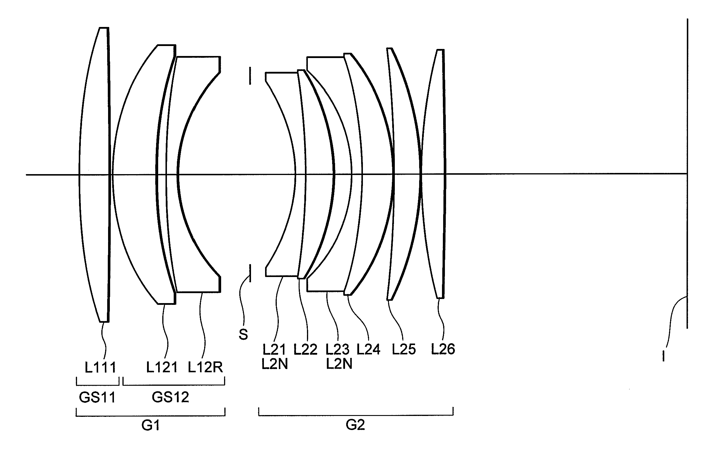
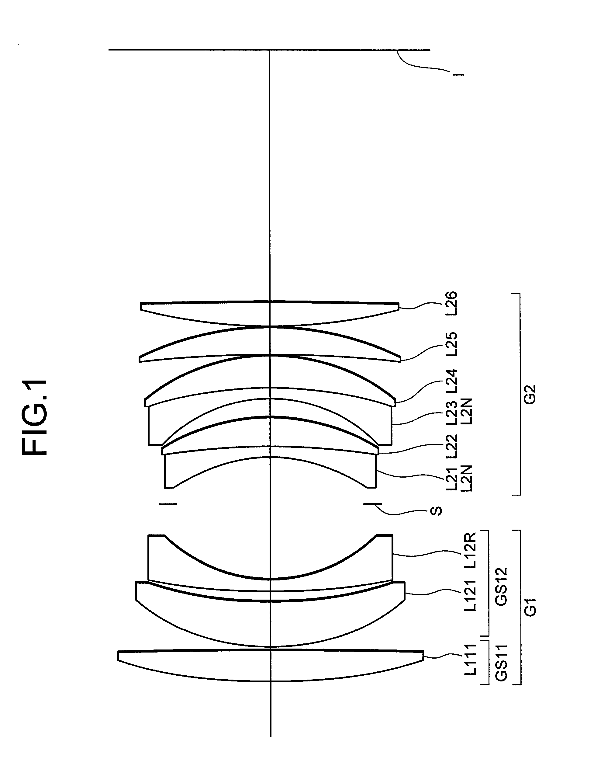
[0152]FIG. 1 is a sectional view showing a lens configuration of a lens system according to Example 1.

[0153]The lens system according to Example 1 is composed of, in order from an object side along an optical axis, a first lens group G1 having positive refractive power, and a second lens group G2 having positive refractive power. An aperture stop S is disposed between the first lens group G1 and the second lens group G2.

[0154]The first lens group G1 is composed of, in order from the object side along the optical axis, a sub-lens group GS11 having positive refractive power, which is constructed by a positive meniscus lens L111 having a convex surface facing the object side with stronger refractive power than an image side surface, and a sub-lens group GS12 having negative refractive power, which is constructed by a positive meniscus lens L121 having a convex surface facing the object side with stronger refractive power than the image side surface and a negative meniscus lens L12R hav...

example 2

[0166]FIG. 4 is a sectional view showing a lens configuration of a lens system according to Example 2.

[0167]The lens system according to Example 2 is composed of, in order from an object side along an optical axis, a first lens group G1 having positive refractive power, and a second lens group G2 having positive refractive power. An aperture stop S is disposed between the first lens group G1 and the second lens group G2.

[0168]The first lens group G1 is composed of, in order from the object side along the optical axis, a sub-lens group GS11 having positive refractive power, which is constructed by a positive meniscus lens L111 having a convex surface facing the object side with stronger refractive power than an image side surface, and a sub-lens group GS12 having negative refractive power, which is constructed by a positive meniscus lens L121 having a convex surface facing the object side with stronger refractive power than the image side surface and a negative meniscus lens L12R hav...

example 3

[0175]FIG. 6 is a sectional view showing a lens configuration of a lens system according to Example 3.

[0176]The lens system according to Example 3 is composed of, in order from an object side along an optical axis, a first lens group G1 having positive refractive power, and a second lens group G2 having positive refractive power. An aperture stop S is disposed between the first lens group G1 and the second lens group G2.

[0177]The first lens group G1 is composed of, in order from the object side along the optical axis, a sub-lens group GS11 having positive refractive power, which is constructed by a positive meniscus lens L111 having a convex surface facing the object side with stronger refractive power than an image side surface, and a sub-lens group GS12 having negative refractive power, which is constructed by a positive meniscus lens L121 having a convex surface facing the object side with stronger refractive power than the image side surface and a negative meniscus lens L12R hav...


PUM

PropertyMeasurementUnit
Volumeaaaaaaaaaa
Volumeaaaaaaaaaa
Poweraaaaaaaaaa

Abstract

A lens system comprising, in order from an object side: a first lens group G1; and a second lens group G2 having positive refractive power; the first lens group G1 including a sub-lens group GS11 having positive refractive power, and a sub-lens group GS12 having negative refractive power, the sub-lens group GS12 having negative refractive power including a meniscus lens having a convex surface facing the object side, given conditions being satisfied: an antireflection coating being formed on at least one optical surface in the first lens group G1 and the second lens group G2, and the antireflection coating including at least one layer formed by a wet-process, thereby providing a lens system having high optical performance with excellently correcting various aberrations and suppressing ghost images and flare, and an optical apparatus equipped therewith.

Description

[0001]The disclosure of the following priority application is herein incorporated by reference:[0002]Japanese Patent Application No. 2009-272048 filed on Nov. 30, 2009.BACKGROUND OF THE INVENTION[0003]1. Field of the Invention[0004]The present invention relates to a lens system suitable for an interchangeable lens for a single-lens reflex camera and a photocopy lens, and an optical apparatus equipped with the lens system.[0005]2. Related Background Art[0006]A so-called double-Gauss type lens system has been used as a lens system used for an interchangeable lens for a single-lens reflex camera and a photocopy lens, and a lot of lens systems have been proposed in such as Japanese Patent Application Laid-Open No. 2007-333790. Regarding such a double-Gauss type lens system, request for suppressing ghost images and flare, which deteriorate optical performance, as well as aberrations becomes increasingly strong. Accordingly, a higher optical performance is required to antireflection coati...

Claims


Application Information

Patent Timeline
IPC IPC(8): G02B1/11B05D5/06G02B1/111G02B13/00
CPCG02B1/115G02B27/0018G02B13/00G02B9/08
Inventor TANAKA, ISSEIOBAMA, AKIHIKO
Owner NIKON CORP
Why Eureka
Try Eureka