
Global Link Connector System

a global link and connector technology, applied in the direction of connection contact material, coupling device connection, instruments, etc., can solve the problem of making possible more complex system architectures

Active Publication Date: 2011-06-02
DEEPLINC
View PDF4 Cites 33 Cited by
  • Summary
  • Abstract
  • Description
  • Claims
  • Application Information

AI Technical Summary

Problems solved by technology

This wet-connection capability made possible more complex system architectures, but was limited by the inability to disconnect or to reconnect such circuits in under-water conditions.

Method used


Image

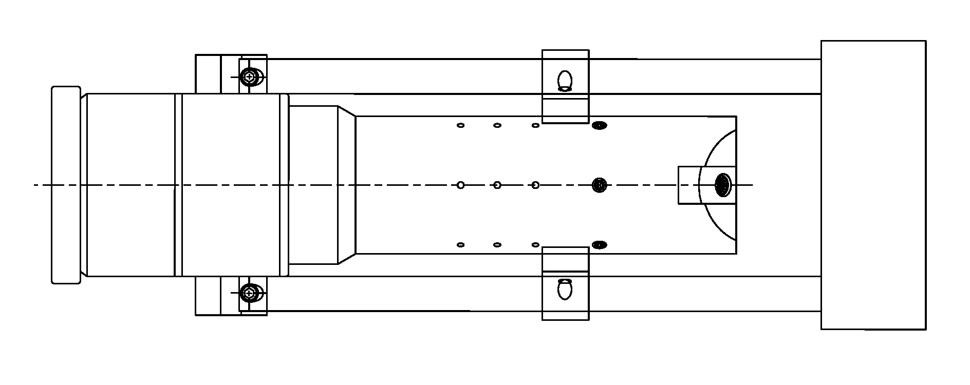
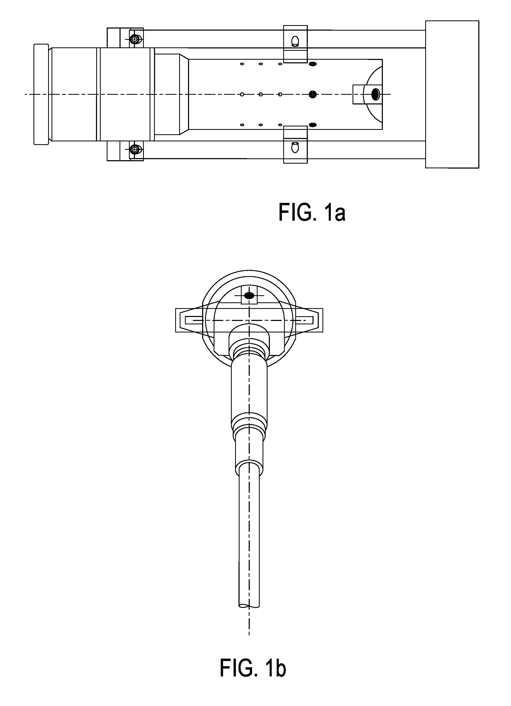
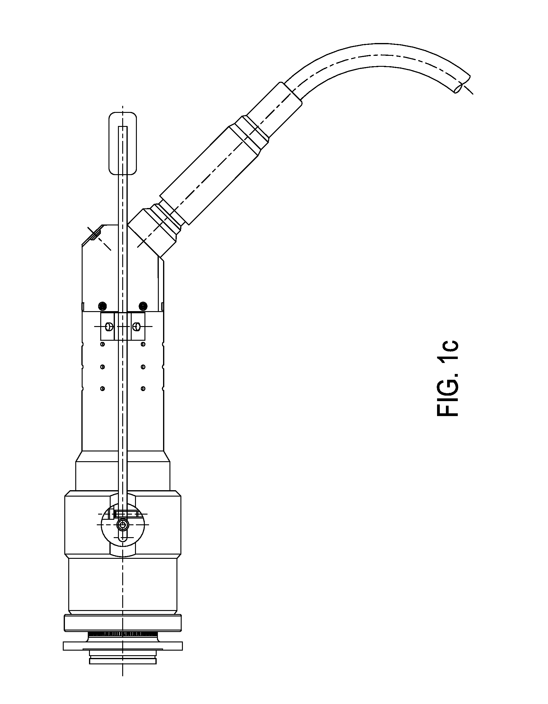
  • Global Link Connector System
  • Global Link Connector System
  • Global Link Connector System

Examples


Embodiment Construction

[0023]The basic operating concept for the mechanical interface of one embodiment of the connector system is illustrated in FIG. 2c, and is described in four sequential drawings. In the first drawing to the left, the scalloped discs represent the plug interface component 1 (far disc) and the receptacle interface component 2 (near disc). The two discs are shown separated, as in a position poised to mate. The plug interface disc 1, in this representation, is still positively seated into the interface end wall of the plug assembly, within an aperture of identical profile geometry. In like manner, The receptacle interface disc 2, in this representation, is still positively seated into the interface end wall of the Receptacle assembly, also within an aperture of identical profile geometry.

[0024]A mating force, applied to both the Plug and Receptacle assemblies, next brings the two interface components together (as represented in the illustration next, to the right). The joining of the two...


PUM


Abstract

A connector mating system that can enable the coupling and decoupling of electrical or optical communications channels, while in a deep, sub-oceanic, sea-floor environments, during which time the contacting interfaces of the said channels remain fully protected from the destructive effects of the said environment. The system features a Wet-Mate Connector (WMC) that provides a means for electrical, optical and hybrid inter-connection within an extremely hostile environments.

Description

[0001]This application includes material which is subject to copyright protection. The copyright owner has no objection to the facsimile reproduction by anyone of the patent disclosure, as it appears in the Patent and Trademark office files or records, but otherwise reserves all copyright rights whatsoever.FIELD OF THE INVENTION[0002]The present invention relates to systems and methods for electrical or optical connectors, and more specifically, to electrical or optical connectors for connections in deep oceanic environments.BACKGROUND OF THE INVENTION[0003]Driven by cost factors, as well as the need to overcome the hazards and complexities associated with joining and switching of multi-circuit cables in deep oceanic environments, the industry was first introduced to Wet-Mateable Connectors (WMC) in the early 1960's. The earliest systems enabled the mating of electrical contacts, in an undersea environment through the use of electrical contacts protected by a dense grease medium, wh...

Claims


Application Information

Patent Timeline
Patent Type & Authority Applications(United States)
IPC IPC(8): G02B6/38H01R13/523
CPCG02B6/3816H01R13/523H01R13/4532G02B6/3817G02B6/389
Inventor TOTH, JOHN R.
Owner DEEPLINC
Learn More