Coverage Gap Detection In Wireless Networks

a technology of wireless network and gap detection, applied in the field of communication, can solve problems such as antenna malfunction, system alarm, and base station antenna out of alignment, and achieve the effect of detecting gaps in wireless network coverage and detecting coverage problems

Inactive Publication Date: 2011-06-02
ALCATEL-LUCENT USA INC
View PDF5 Cites 10 Cited by
  • Summary
  • Abstract
  • Description
  • Claims
  • Application Information

AI Technical Summary

Problems solved by technology

Over time, and especially after a storm with strong winds, base station antennas may go out of alignment.
This situation may result in sub

Method used


Image

  • Coverage Gap Detection In Wireless Networks
  • Coverage Gap Detection In Wireless Networks
  • Coverage Gap Detection In Wireless Networks

Examples


Embodiment Construction

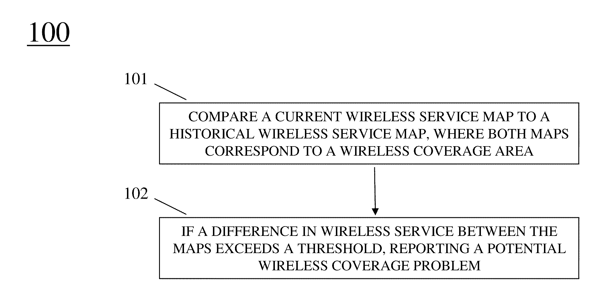
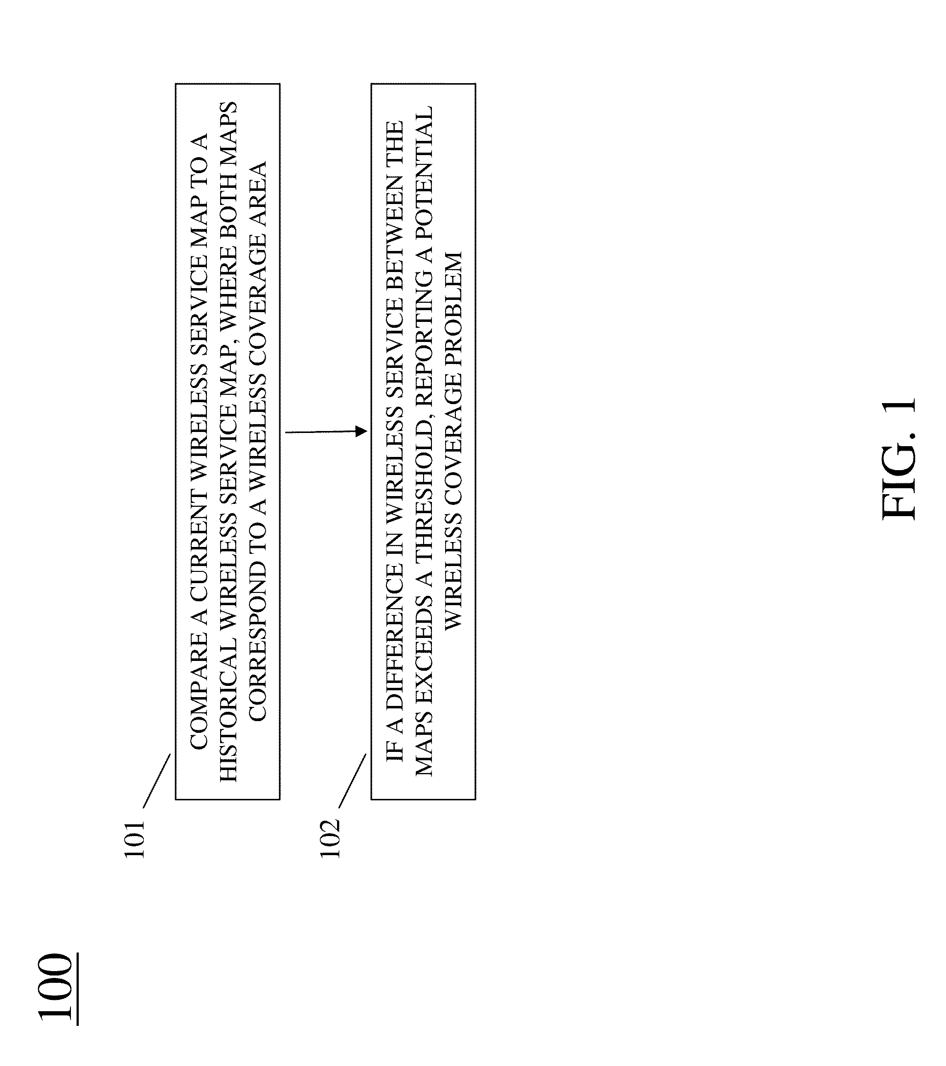
[0011]The present invention can be more fully understood with reference to FIGS. 1-6. FIG. 1 is a logic flow diagram of functionality performed in accordance with various embodiments of the present invention. Diagram 100 serves as a good generalization of many of the embodiments described in detail herein below. Thus, it is referenced now to provide a preview of the general approach to wireless coverage gap detection followed by many embodiments of the present invention. In diagram 100, network equipment compares (101) a current wireless service map to a historical wireless service map, where the current wireless service map and the historical wireless service map correspond to the same wireless coverage area. If a difference in wireless service between the current wireless service map and the historical wireless service map exceeds a threshold, a potential wireless coverage problem is reported (102). Such an approach may be able to detect network performance problems related to ant...


PUM


Abstract

Embodiments are described herein to provide a general approach to wireless coverage gap detection. One general approach involves network equipment comparing (101) a current wireless service map to a historical wireless service map, where the current wireless service map and the historical wireless service map correspond to the same wireless coverage area. If a difference in wireless service between the current wireless service map and the historical wireless service map exceeds a threshold, a potential wireless coverage problem is reported (102). Such an approach may be able to detect network performance problems related to antenna misalignment/malfunction in an effort to minimize the service interruption to subscribers.

Description

FIELD OF THE INVENTION[0001]The present invention relates generally to communications and, in particular, to detection of coverage problems in wireless communication systems.BACKGROUND OF THE INVENTION[0002]Over time, and especially after a storm with strong winds, base station antennas may go out of alignment. See, for example, wireless network 200 in FIG. 2. This situation may result in sub-optimal RF coverage, which degrades overall system performance. Moreover, an antenna malfunction may not generate an alarm in the system. (Typically, in the case of an antenna being out of alignment, there are no alarms.) Only after customers start complaining about poor coverage, do operators take action. First, drive testing is performed to detect and verify the problem, and then finally a skilled technician is sent to repair the antenna. Thus, an approach that is better able to detect wireless coverage problems in networks is desirable.BRIEF DESCRIPTION OF THE DRAWINGS[0003]FIG. 1 is a logic...

Claims


Application Information

Patent Timeline
IPC IPC(8): G06F15/16G06F17/30
CPCH04W28/04H04W24/00
Inventor SANDERS, SUSAN W.MUKHOPADHYAY, AMIT
Owner ALCATEL-LUCENT USA INC
Why Eureka
Try Eureka