One-piece integrated composite wall foundation and floor slab system

a composite wall and floor slab technology, applied in the direction of building roofs, building reinforcements, constructions, etc., can solve problems such as compromise of joint functions, and achieve the effect of reducing cost and effor

Active Publication Date: 2011-06-09
EASI SET INDS
View PDF5 Cites 0 Cited by
  • Summary
  • Abstract
  • Description
  • Claims
  • Application Information

AI Technical Summary

Benefits of technology

[0007]It is therefore an object of the present invention to provide a combination or composite wall foundation and floor slab structure or module which can be assembled with other modules and which can be pre-stressed and post-tensioned into a unitary, integral structure for a building of substantially any size and which can be disassembled, transported and reassembled with a minimum of cost and effort.
[0008]It is a further object of the invention to provide a composite floor slab and wall foundation structure of increased strength and integrity at a transition between the structure functioning principally as a wall foundation and the structure functioning principally as a floor slab.

Problems solved by technology

However, if such a slab or other structure is formed within the perimeter of a foundation structure, it will usually be at least imperfectly integral therewith even if some structural connection is provided; allowing differential settling of the slab or other structure relative to the foundation and / or moisture seepage between the foundation and slab or other structure.
The desired size of a structure may require conventional techniques to be performed in a manner which may compromise the joint functions of the wall foundation and the floor slab to support the building and provide a load bearing barrier.
Additionally, since most such structures are built in response to a recognized or anticipated need, the time required for providing a suitable foundation and slab is an important factor in the building of any structure and may not be adequately satisfied with in-situ construction techniques, particularly in view of the time and labor required for concrete finishing (e.g. to obtain the desired surface finish or texture) and the time required for curing of the concrete to attain sufficient strength for further construction to be performed (usually on the order of several days although concrete will continue to cure and increase in strength over a period of weeks or months).

Method used


Image

  • One-piece integrated composite wall foundation and floor slab system
  • One-piece integrated composite wall foundation and floor slab system
  • One-piece integrated composite wall foundation and floor slab system

Examples


Embodiment Construction

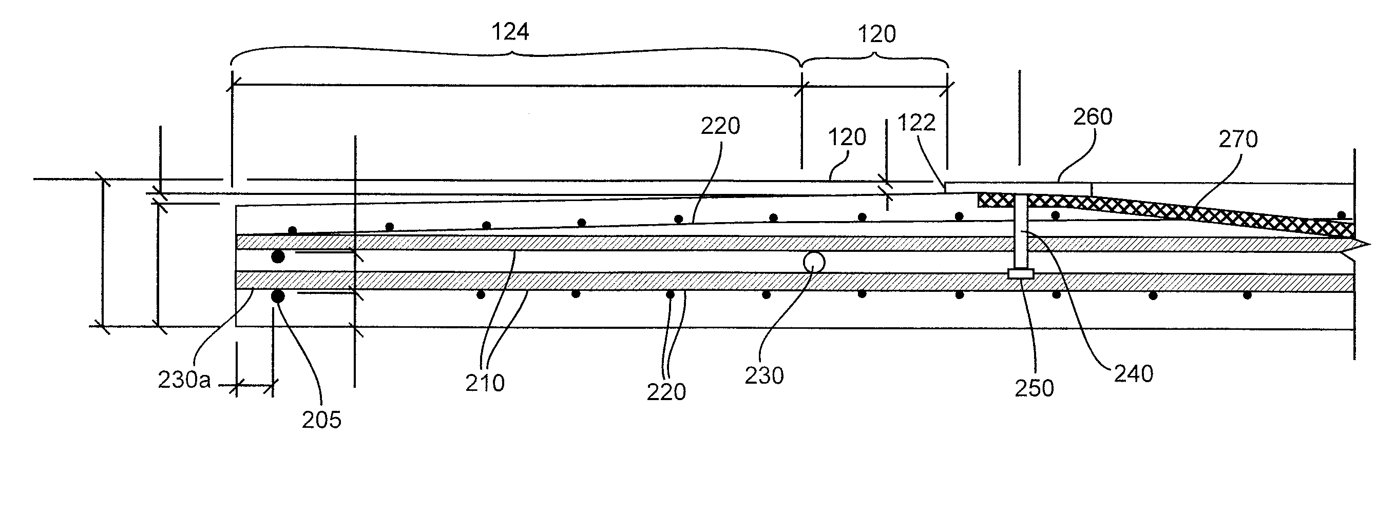
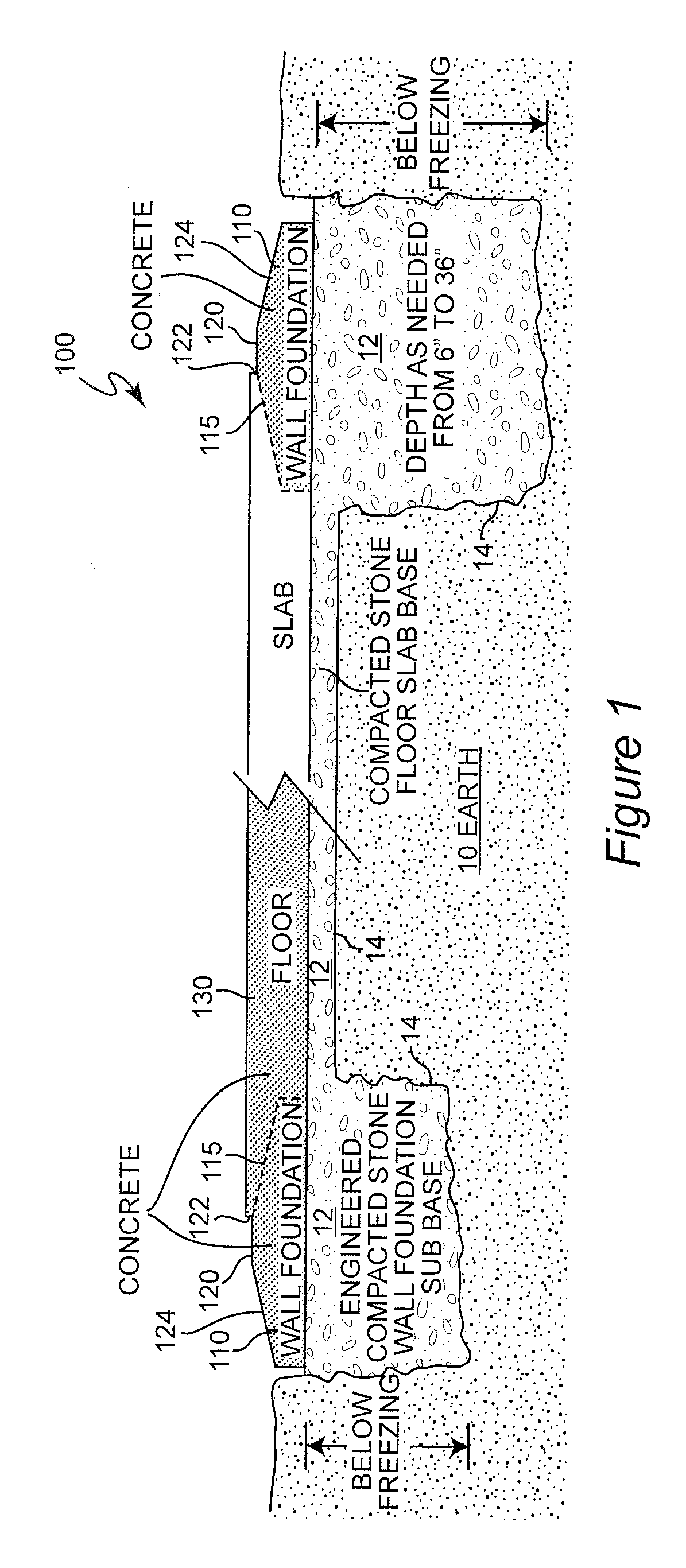
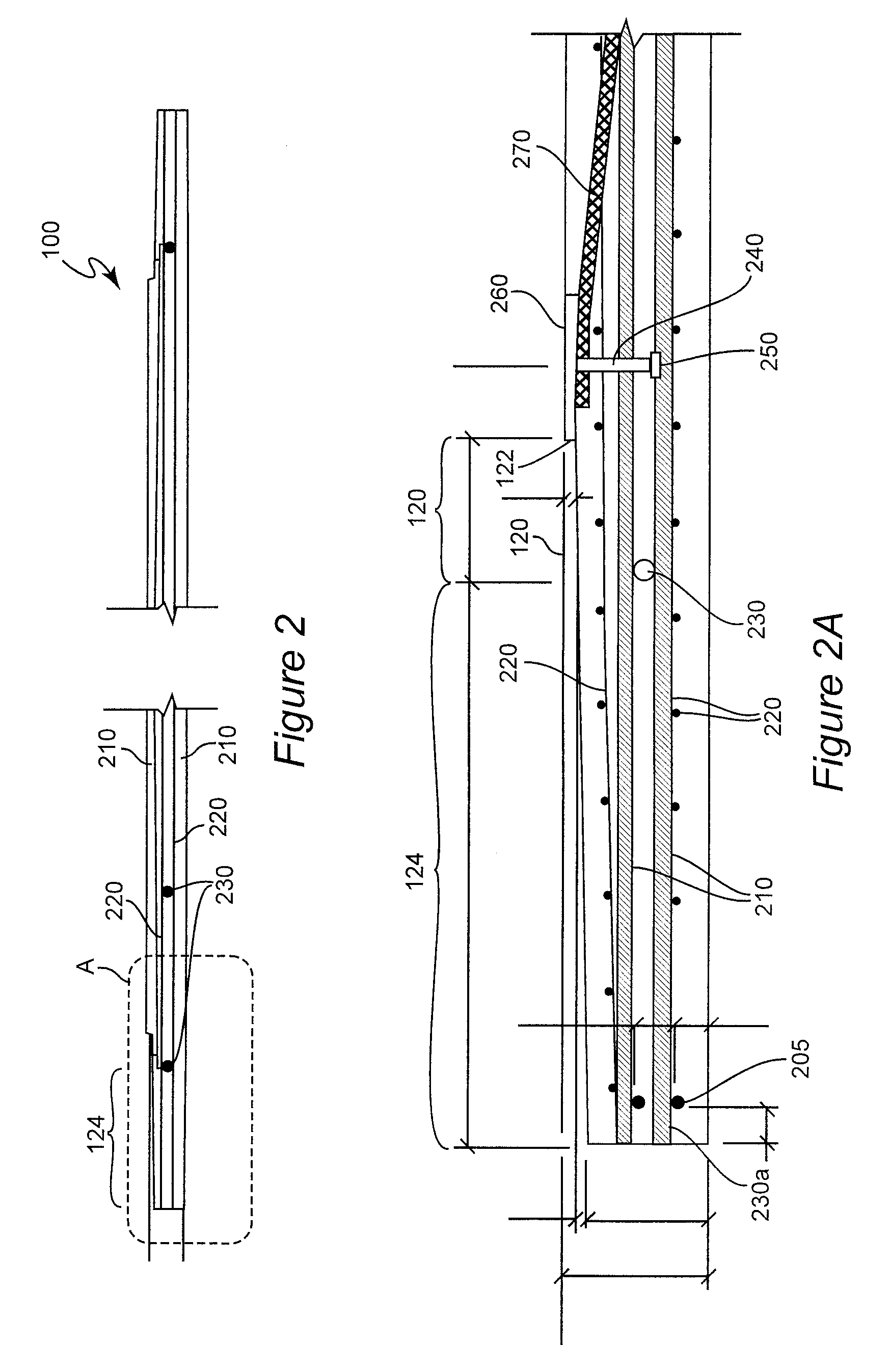
[0018]Referring now to the drawings, and more particularly to FIG. 1, there is shown a generalized cross-sectional view of the composite wall foundation and floor slab in accordance with the invention (but with internal details of the wall foundation and floor slab structure omitted for clarity) as preferably installed at a building site. Preferred internal details of the composite wall foundation and floor slab are illustrated in detail in FIGS. 2-4B and will be discussed in detail below. It should be understood that the depiction of the invention is neither to scale or illustrative of desired proportions; the geometry of some features of the invention being exaggerated for clarity.

[0019]The overall shape of the composite wall foundation and floor slab or a module thereof 100 (sometimes collectively referred to hereinafter, for brevity, as a foundation / slab or foundation / slab module) is a rectangular sheet of a thickness as may be required by anticipated load conditions. The edges ...


PUM


Abstract

A unitary, composite wall foundation and floor slab structure and system is provided by a pre-stressed cast concrete structure having a wall foundation region, a floor slab region and a transitional region therebetween and strands passing through all of those regions. One or more such structures are also post-tensioned using cables passing through tube embedded in the cast concrete structure and, when a plurality of such structures are employed in a modular manner, such post-tensioning draws all such modules into a larger unitary composite wall foundation and floor slab structure. The transition region may be further reinforced by angular reinforcing elements. Intermediate and end sections of varied shape may be used to complete the structure.

Description

CROSS-REFERENCE TO RELATED APPLICATIONS[0001]This application claims priority of the filing date of U. S. Provisional Patent Application 61 / 266,369, filed Dec. 3, 2009, which is hereby incorporated by reference in its entirety.FIELD OF THE INVENTION[0002]The present invention generally relates to prefabricated wall foundation and floor slab components for buildings and, more particularly, to an integrated composite, one-piece, combination floor slab and wall foundation structural component utilizing pre-stressing and post-tensioning, and optionally but preferably, an engineered compacted stone sub-base extending at least below a frost or freeze line or depth to produce a combined or composite wall foundation and floor slab for buildings of substantially any size.BACKGROUND OF THE INVENTION[0003]Many structures have been built of many different types of materials and of widely varying sizes and designs for many different purposes and many others are foreseeable. All such structures w...

Claims


Application Information

Patent Timeline
Patent Type & Authority Applications(United States)
IPC IPC(8): E04C5/08E04B1/20
CPCE02D27/02
Inventor SMITH, RODNEY I.
Owner EASI SET INDS
Why Eureka
Try Eureka