Heat transfer core for water cooling tower

Inactive Publication Date: 2003-05-29
SMITH KENYON P +1
View PDF25 Cites 0 Cited by
  • Summary
  • Abstract
  • Description
  • Claims
  • Application Information

AI Technical Summary

Problems solved by technology

Ejected cooled water reduces the efficiency of the cooling tower.
A corrugated pattern on side edges provides the opportunity for the loss of cooled water, while an edge bar reduces that opportunity.
During operation of a water cooling t

Method used


Image

  • Heat transfer core for water cooling tower
  • Heat transfer core for water cooling tower
  • Heat transfer core for water cooling tower

Examples


Example

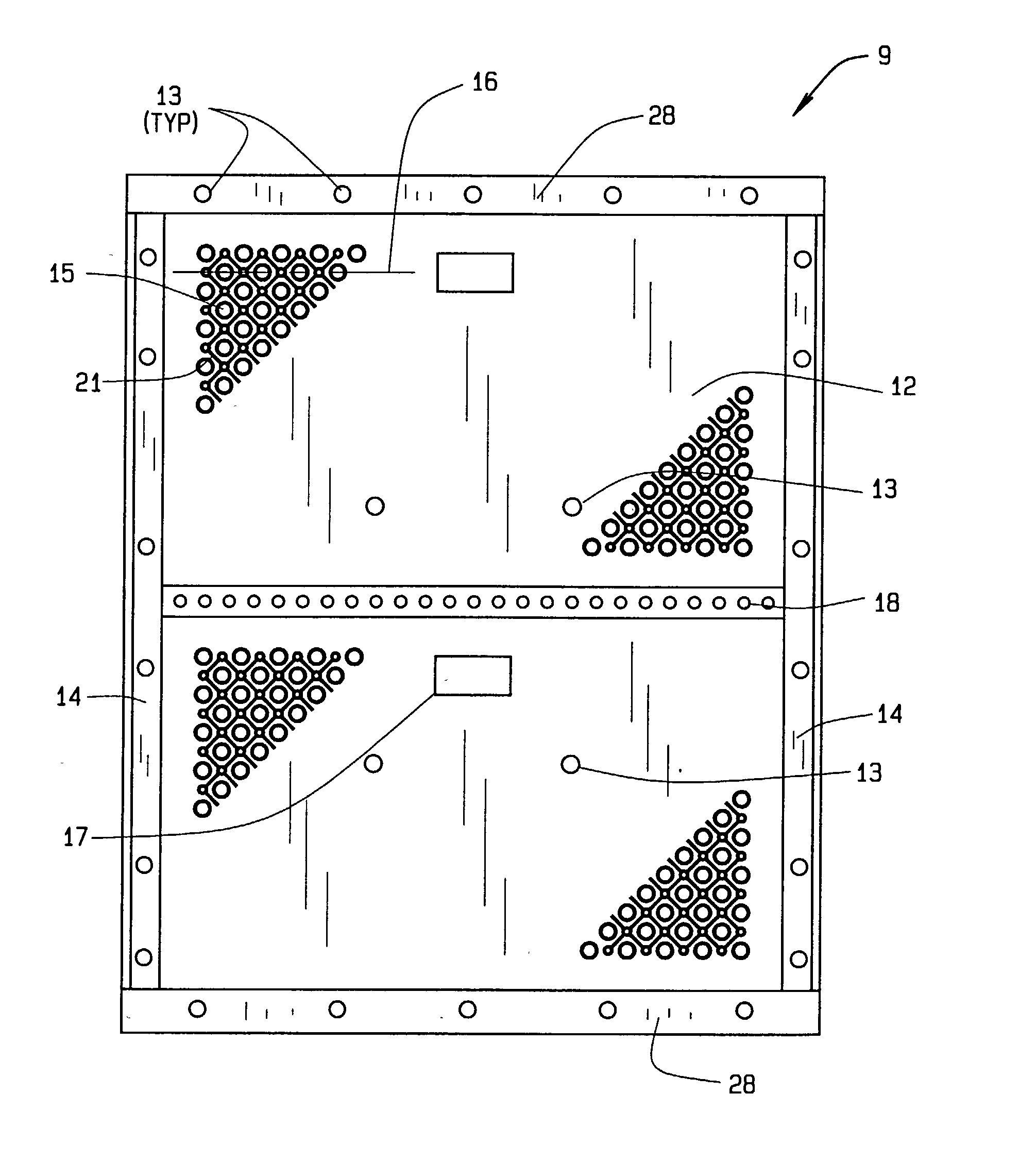
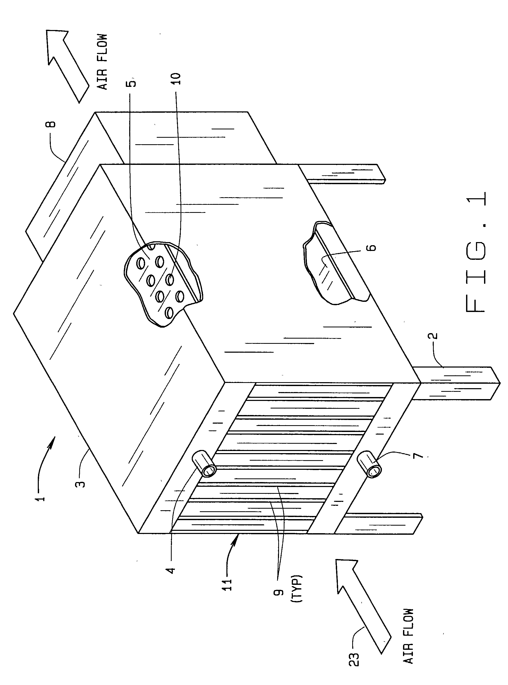
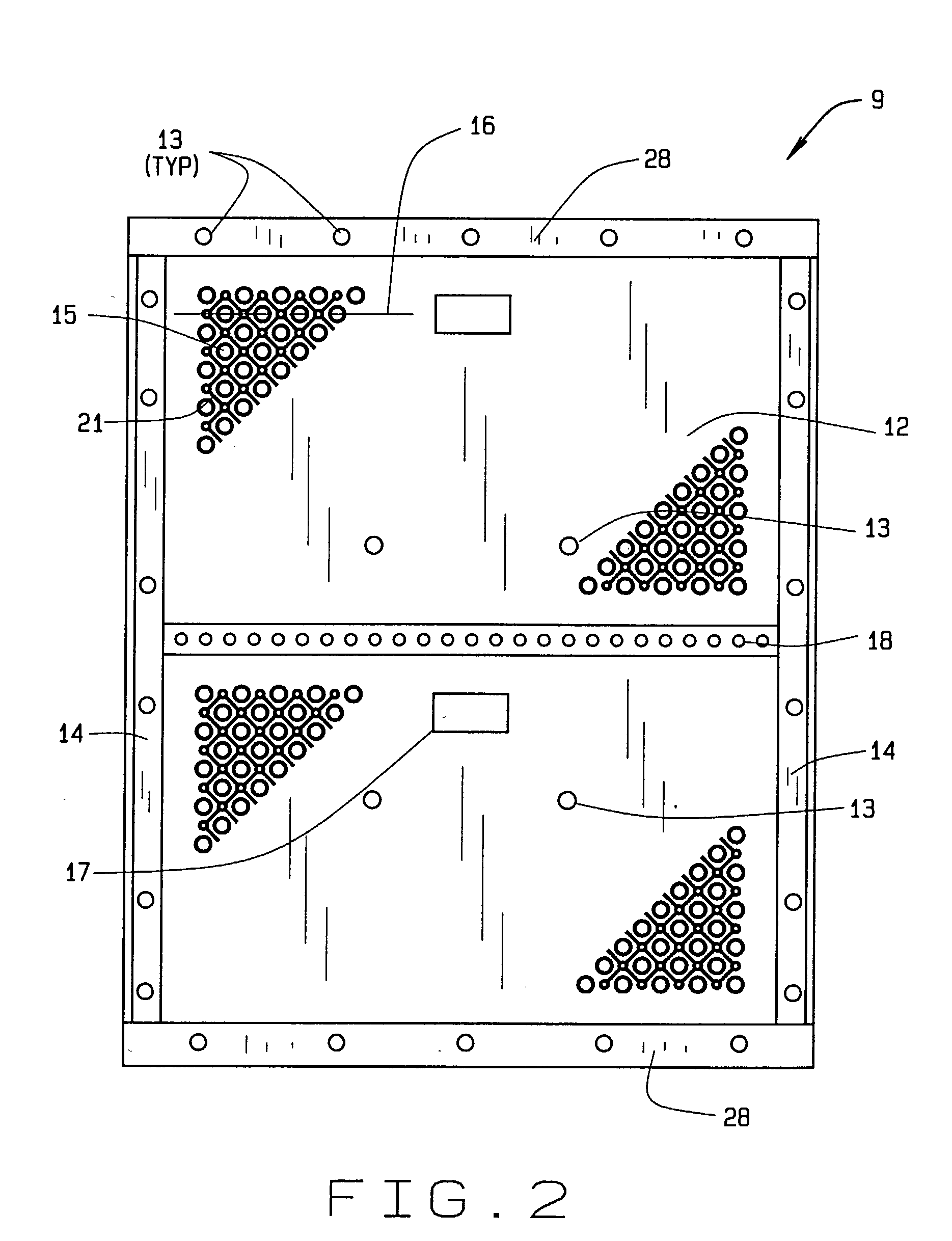
[0031] Referring to the drawings, FIG. 1 shows a cooling tower 1 which receives heated water from an industrial, an air conditioning, or a refrigeration application so as to cool the water. The cooling tower cools the heated water by means of exposing the heated water to air drawn or forced through the cooling tower and then returning the cooled water to the industrial, air conditioning, or refrigeration application. The cooling tower 1 has a frame 2, a cabinet 3, a heated water inlet 4, an upper heated water reservoir 5, a lower cooled water reservoir 6, a cooled water outlet 7, and a blower 8. The frame 2 has legs or channels that attach the cooling tower 1 to a foundation, typically a roof. The legs, in the alternative, could be in the form of a bent sheet or removed completely. In this invention, a cooling tower 1 has a film fill pack 11 of the present invention disposed within a cabinet 3 between the reservoirs 5 and 6 for directing a flow of heated water from the upper heated ...


PUM

PropertyMeasurementUnit
Thicknessaaaaaaaaaa
Thicknessaaaaaaaaaa
Thicknessaaaaaaaaaa

Abstract

A heat transfer core for a water-cooling tower has a film fill sheet made from formed resin. The sheet then has a pattern of buttons, channels, dimples, and spacers formed on one surface of the sheet. Along the edges of the sheet, stiffening bars with spacers are formed. The sheets are positioned upright, spaced horizontally between the upper heated water and the lower cooled water reservoirs for a generally horizontal flow of cooling air across films of water flowing downwardly over the film fill sheets. The buttons, channels, and dimples direct water across the sheet to flow down in a meandering manner and to increase the length of time for water to descend the sheet and thereby maximize cooling.

Description

[0001] A claim of priority is made based on U.S. Provisional Application No. 60 / 333,385, filed Nov. 26, 2001.[0002] Not applicable.[0003] 1. Field of the Invention[0004] This invention relates to heat transfer core for water cooling towers, and especially to film fill pack having so-called film fill sheet that brings heated water into contact with flowing air for an increased time to maximize cooling of the water.[0005] In a water cooling tower, heated water enters the tower from a source. Such heated water may be a byproduct of a manufacturing process or of an environmental cooling system, such as an air conditioning or refrigeration system. Through use of airflow, the cooling tower transfers heat from the water to the atmosphere. The cooled water then returns to the source to remove more heat in a repeating cycle. Airflow in cooling towers has two forms: cross-flow and counter flow. Cross-flowing air passes substantially laterally across the flow of the heated water. Counter-flowi...

Claims


Application Information

Patent Timeline
IPC IPC(8): F28F25/08
CPCF28F25/087Y10T428/24669Y10S261/72Y10T428/31739
Inventor SMITH, KENYON P.SMITH, ROBERT G.
Owner SMITH KENYON P
Why Eureka
Try Eureka