Microtreatment of iron-based alloy, apparatus and method therefor, and articles resulting therefrom
a technology of iron-based alloys and micro-treatment, which is applied in the field of micro-treatment of iron-based alloys and the field of equipment therefor, can solve the problems that the addition of carbon is usually detrimental to the welding characteristics and the strength of steels cannot be achieved, and achieve the effect of reducing cost, time and effort, and high strength
- Summary
- Abstract
- Description
- Claims
- Application Information
AI Technical Summary
Benefits of technology
Problems solved by technology
Method used
Image
Examples
third embodiment
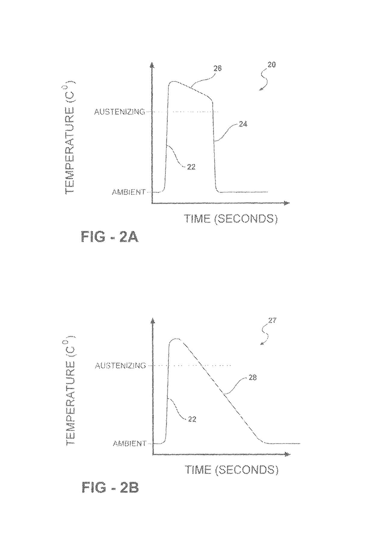
[0070]As dual / multi phase steels are currently made on continuous annealing lines, Colascitic steel sheet and workpieces could be created by reheating in accordance with the present invention. The partially austenized sheet / workpiece could be quenched to yield a combination of highly tempered Colascite and other austenite daughter phases. If the temperature is rapidly raised to A2 followed by a rapid quench, a dual phase workpiece might be comprised of tempered Colascite and untempered Colascite. If the temperature is slowly raised to A2 and then hard quenched in oil, water, or some other suitable medium, the dual phase workpiece might be comprised of untempered martensite and tempered Colascite. If the temperature is slowly raised to A2 and then soft quenched or slowly air cooled, the dual phase workpiece might be comprised of tempered Colascite and a combination of pearlite, ferrite, martensite, retained austenite or other austenitic daughter phases. While the possible options are...
second embodiment
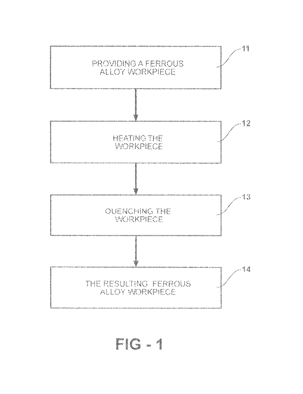
[0096]the present invention discloses a pressure forming method of making high percentage Colascite ferrous alloy near net shape part and an apparatus for making the same, denoted as “Warm Forming”. As shown in FIG. 13, the process of making Colascite ferrous alloy near net shape part includes providing an initially Colascite ferrous alloy workpiece 151, heating the workpiece below the austenite conversion temperature 152, placing the non-austenized sheet of ferrous alloy in the open forming apparatus 153, operating the apparatus to form a near net shaped part from the non-austenized Colascite sheet 154, optionally quenching the workpiece to the ambient temperature, or some other determined temperature cool enough to prevent distortion of the part 155, and then opening the pressure forming apparatus and removing the near net shaped Colascite form 156. A step of tempering 157 may be optionally later included to relieve stresses and prevent cracking of the resulting workpiece. The tem...
first embodiment
[0127]In the spirit of the first embodiment, the non-Colascite workpiece is either heated by induction to about 900° C. to 1290° C. and placed on the lower die 252 or the temperature controlled fluid from the hydraulic pressure unit 253 rapidly heats the workpiece to about 900° C. to 1290° C. when the workpiece is placed in the closing die. The heated non-Colascite material is stretched by the heated hydraulic fluid until it contacts the temperature controlled upper die. The upper die quenches the non-Colascite steel to form the Colascite microstructure. Cooling means 256 reduces the temperature of the final formed part 254 to a temperature at which its shape will remain stable, usually below 315° C. Again, although in this embodiment, the heating source is induction or heated fluid convection, any suitable heating means may be used. This example will be recognized as a very simplistic example of a liquid punch hydroform die to those skilled in the art.
[0128]FIG. 24 shows a third em...
PUM
| Property | Measurement | Unit |
|---|---|---|
| temperature | aaaaa | aaaaa |
| temperature | aaaaa | aaaaa |
| temperature | aaaaa | aaaaa |
Abstract
Description
Claims
Application Information
 - R&D
- Intellectual Property
- Life Sciences
- Materials
- Tech Scout
- Unparalleled Data Quality
- Higher Quality Content
- 60% Fewer Hallucinations
Browse by: Latest US Patents, China's latest patents, Technical Efficacy Thesaurus, Application Domain, Technology Topic, Popular Technical Reports.
© 2025 PatSnap. All rights reserved.Legal|Privacy policy|Modern Slavery Act Transparency Statement|Sitemap|About US| Contact US: help@patsnap.com


